3 rs485-1 line reception, rs485-2 line repetition, 4 rs485 tx/rx line, 6 serial terminations/connections – Videotec ULISSE PLUS User Manual
Page 25: Y units ( "7.4.5.3 rs485-1, Line reception, rs485-2 line repetition, Tion on rs485-1 line ( "7.4.5.4
EN - English - I
nstruc
tions manual
23
7.4.6 Serial terminations/connections
The diagram shows two dip-switches that are used to
configure termination of the serial line.
Every peripheral that is situated at the end of a line
must be terminated using the appropriate dip-switch
in order to prevent signal reflection and distortion.
dip-switches 1 and 2 terminate serial lines RS485-1
and RS485-2 respectively.
j
Unlike the previous cases in this table when
the dip-switch rocker is up it represents the
value 0 (OFF) while if the rocker is down it
represents the value 1 (ON).
TERMINATION OF RS485 LINES
Description
DIP 2 DIP 1
Configuration
Line RS485-1
-
ON
Terminated
-
OFF
Not terminated
Line RS485-2
ON
-
Terminated
OFF
-
Not terminated
Tab. 11
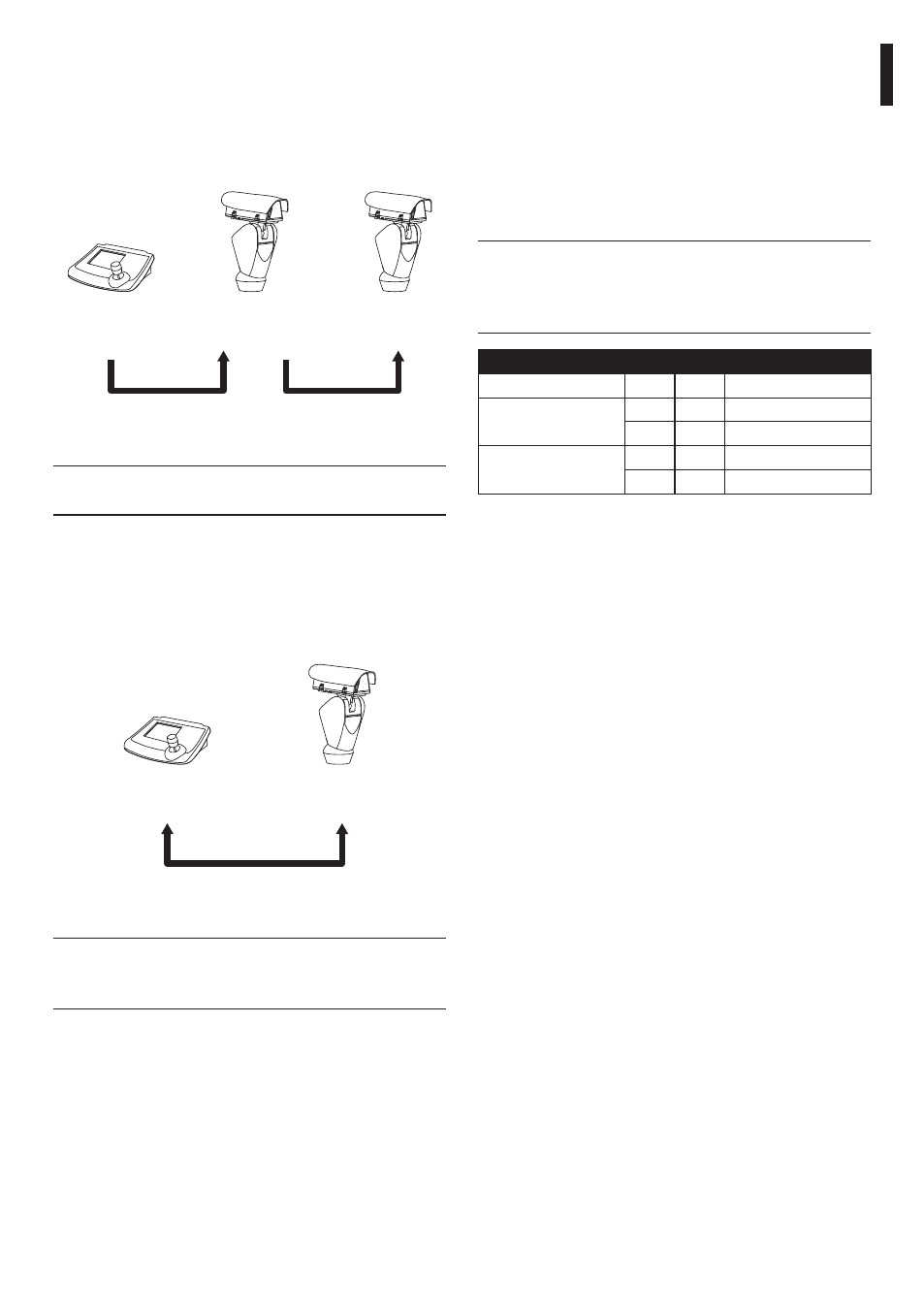
7.4.5.3 RS485-1 line reception, RS485-2 line
repetition
With this type of setting it is possible to connect more
than one device in cascade. The signal is repeated
from every unit, making it possible to markedly
increase total distance.
RS485-1
Max 1200m
Max 1200m
RS485-1 RS485-2
Control
Keyboard
Fig. 41
j
It only works with mono-directional
protocols.
7.4.5.4 RS485 TX/RX line
With this type of setting it is possible to obtain a
bi-directional, half/duplex, communication on the
RS485-1 line.
The RS485-2 serial line is not used.
RS485-1
Max 1200m
TX/RX
Control
keyboard
Fig. 42
j
This function is only available for
bi-directional protocols (e.g. PELCO,
AMERICAN DYNAMICS, Macro, etc.).