2 power supply connection 24vac, 3 power supply connection 120/230vac, 4 video cable connection – Videotec ULISSE PLUS User Manual
Page 20
EN - English - I
nstruc
tions manual
18
7.2.3.2 Power supply connection 24Vac
Connect the power supply cables as described in the
table below.
POWER SUPPLY CONNECTION 24VAC
Colour
Terminals
Defined by the installer
(N) Neutral
Defined by the installer
(L) Phase
Yellow/Green
Earth
Tab. 04
h
Only for products marked UL intended for
the North American market, use a class 2 UL
listed transformer.
7.2.3.3 Power supply connection
120/230Vac
Connect the power supply cables as described in the
table below.
POWER SUPPLY CONNECTION 120/230VAC
Colour
Terminals
Blue
(N) Neutral
Brown
(L) Phase
Yellow/Green
Earth
Tab. 05
h
Use the appropriate junction-box
UPTJBUL to connect the power supply
line. For further information, refer to the
product use and installation manual.
7.2.4 Video cable connection
h
The installation is type CDS (Cable
Distribution System), do not connect it to
SELV circuits.
h
In order to reduce the risk of fire, only
use cable sizes greater than or equal to
26AWG.
h
Connect the screen and central cable
respectively to the GND and VIDEO
terminals. The terminals accept cables
with sections between 0.5 mm2 (AWG20)
and 0.08 mm2 (AWG28).
h
Earth cable should be about 10mm longer
than the other two, so that it will not be
disconnected accidentally if the cable is
stretched or pulled.
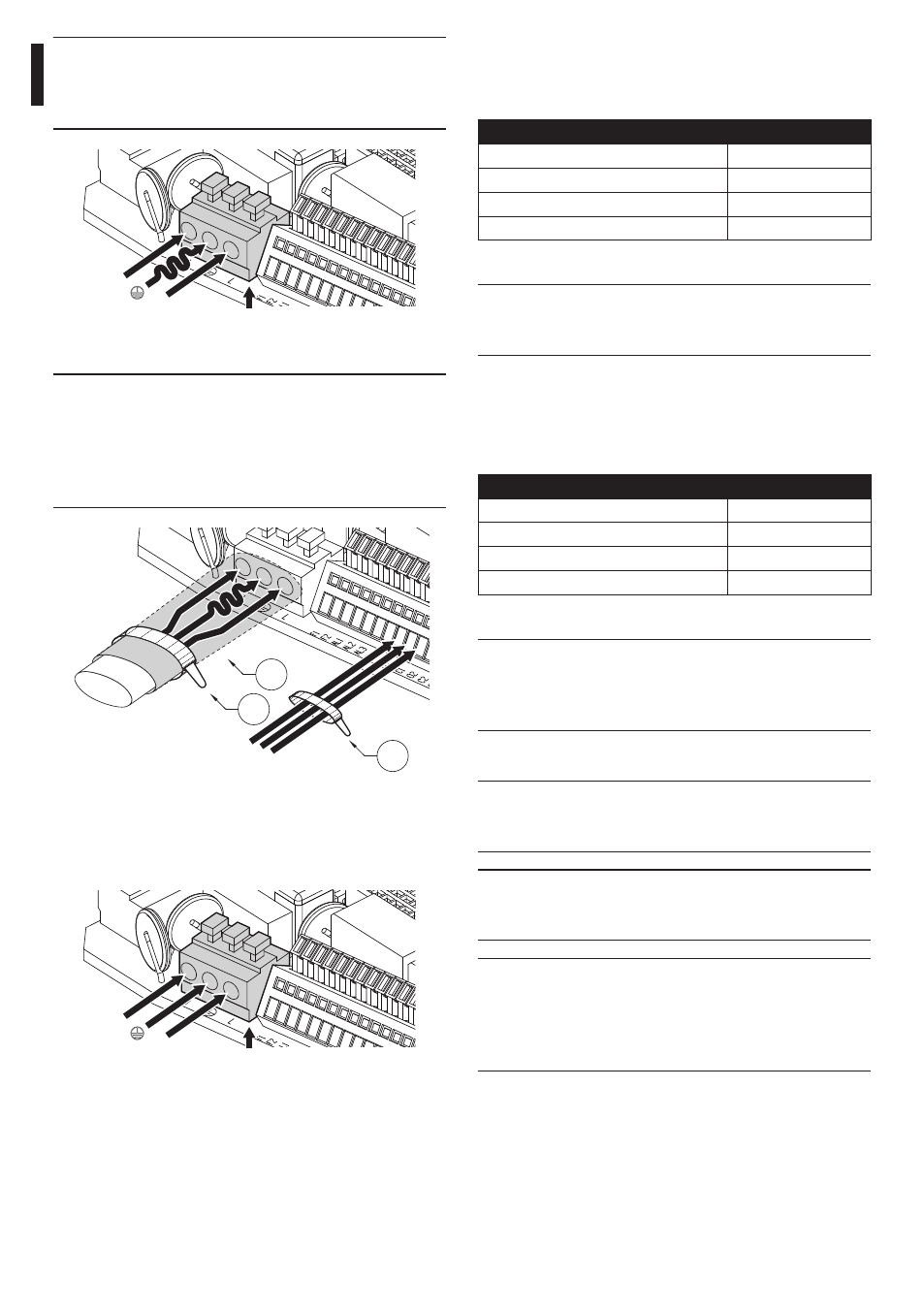
a
Power
Fig. 25
h
The power supply cable should also be
covered by the silicone sheath (01) supplied
for this purpose, and fastened with the
corresponding tie (02). Furthermore, all
signal cables must be grouped together by
means of a strap (03).
03
01
02
Fig. 26
Cut the cables to the correct length and make the
connections. Connect the power supply to the J1
terminal.
L
N
a
Power
Fig. 27