2 connection of the camera and motorised lens, 1 motorised lens ptz board, 2 connector for camera/motorised lenses – Videotec ULISSE PLUS User Manual
Page 16
EN - English - I
nstruc
tions manual
14
7.1.2.2 Connector for camera/motorised
lenses
h
All connections illustrated below should
be made only and exclusively by expert
installers who should comply with all the
wiring and power supply specifications for
the devices.
The electronics board is designed to control cameras
with motorised lenses (Focus, Iris, Zoom), which
may or may not have potentiometers to control the
position reached.
Before making the connections make sure that the
voltages supplied by the board fall within the limits
allowed for the apparatus.
CONNECTOR FOR CAMERA/MOTORISED LENSES
Camera power supply
+12V - 800mA max
Lens potentiometer power
supply
+5V - 15mA max
Lens motor power supply
6-15V (adjustable) - 200mA
max (Focus+ Zoom+Iris)
Tab. 02
In the case of lenses with reverse polarity motors,
connect as shown in the following drawing:
FOCUS +
FOCUS -
IRIS +
IRIS -
ZOOM +
ZOOM -
+
M
+
M
+
M
Fig. 13
CN2.
In the case of lenses with common wire motors,
enable the corresponding menu option ("9.6.3 ZFI
camera settings menu", page 28) and connect as
shown in the following drawing:
FOCUS +
FOCUS -
IRIS +
IRIS -
ZOOM +
ZOOM -
+
M
+
M
+
M
Fig. 14
CN2.
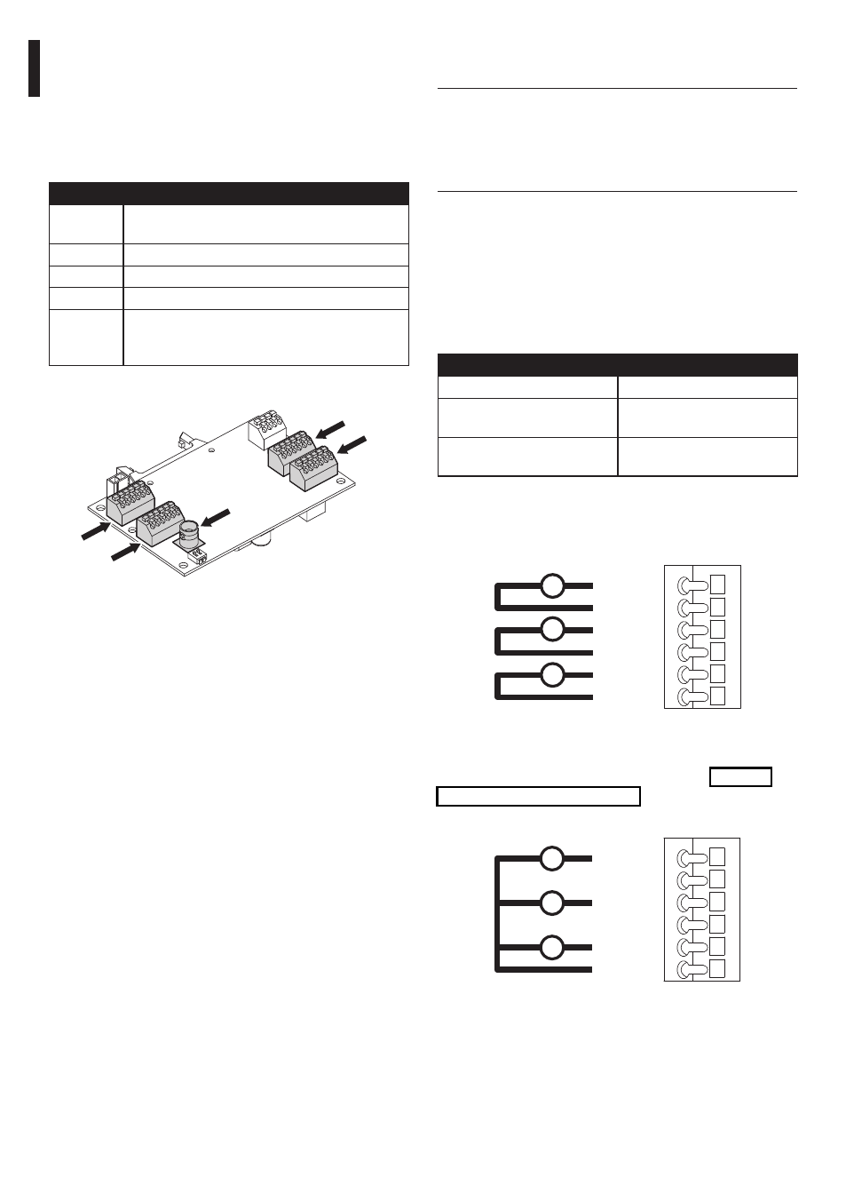
7.1.2 Connection of the camera and
motorised lens
7.1.2.1 Motorised lens PTZ board
The following is a description of the electronics board
inside the housing, which controls all functions of the
motorised lens.
CODE
DESCRIPTION
CN1
BNC connector for connecting the video signal
from the camera
CN2
Motorised lens motor control connector
CN3
Motorised lens potentiometer connector
CN6
Serial connector for controlling the camera
CN7
Camera power supply, clean contact for
activating the camera night mode, additional
lines
Tab. 01
CN7
CN2
CN1
CN6
CN3
Fig. 12