HP XP Array Manager Software User Manual
Page 32
*
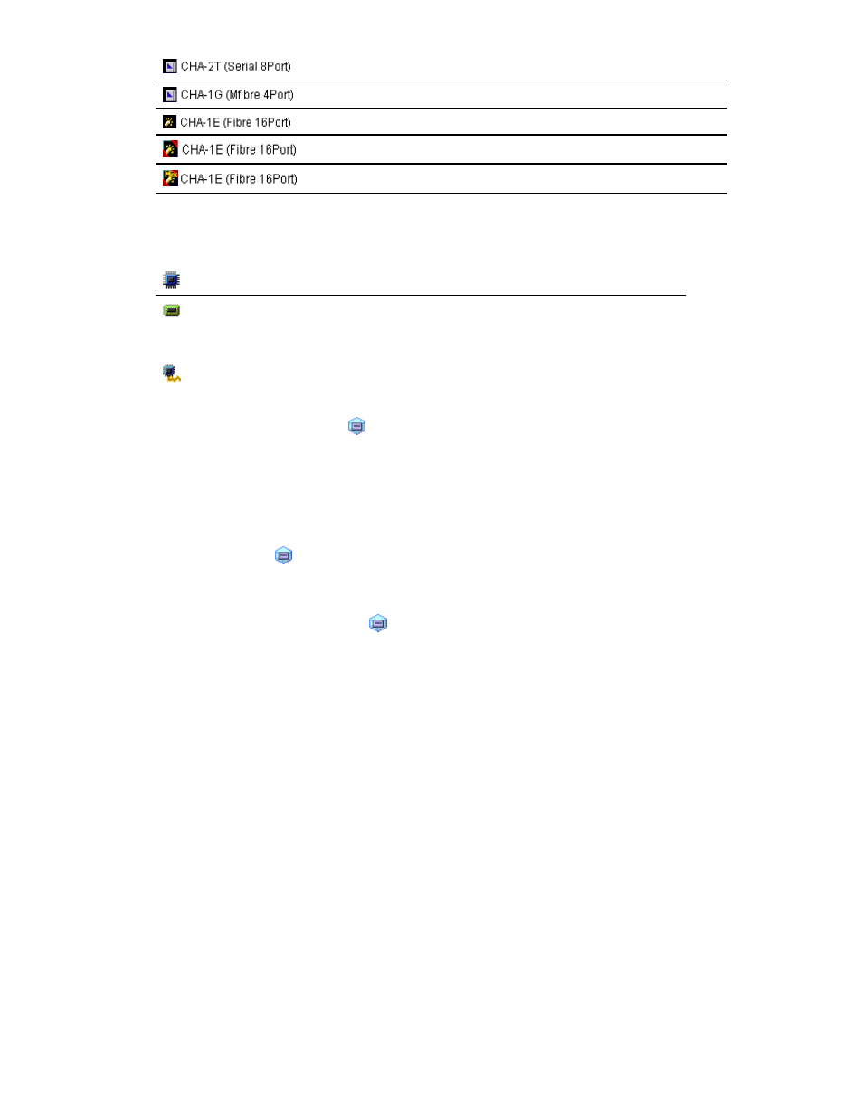
an ESCON channel adapter
* a FICON channel adapter
*
a Fibre Channel adapter in Standard mode
* a Fibre Channel adapter in High Speed mode
* a Fibre Channel adapter in Initiator/External MIX mode
* The channel adapter number and number of ports that displayed on the right side of the icon are
examples.
• Icons displayed below the DKA folder:
a disk processor (DKP)
a data recovery and reconstruction processor (DRR)
• Icon displayed below the Access Path Usage folder:
an access path
No icon is displayed below the Cache folder.
The numbers on the right of icons ( ) displayed below the Parity Group or External Group
folder are IDs of parity groups or external volume groups. The letter E at the beginning of an ID
indicates that the group is an external volume group.
Note:
A volume existing in an external storage system and mapped to a volume in the storage
system by using External Storage is called an external volume. An external volume group is a
group of external volumes for managing them and that does not contain any parity information
unlike a parity group. However, Auto LUN window treat external volume groups same as parity
groups for convenience.
The parity group icon ( ) can represent a single parity group. The parity group icon can also
represent two or more parity groups that are concatenated. If two or more parity groups are
concatenated, volumes can be striped across two or more drives. Therefore, concatenated parity
groups provide faster access (particularly, faster sequential access) to data.
For example, if the parity group icon ( ) indicates a single parity group 1-3, the text 1-3
appears on the right of the icon. If the parity group icon indicates two or more parity groups
that are connected together, all the connected parity groups appear on the right of the icon. For
example, if the parity group 1-3 is connected with the parity group 1-4, the text 1-3[1-4]
appears on the right of the parity group icon. (All the parity groups connected with 1-3 are
enclosed by square brackets).
Note:
Remote Web Console does not allow you to connect two or more parity groups. To use
connected parity groups, contact the service representative.
•
The list displays statistics about parity group usage, processor usage, etc.
If you select connected parity groups in the tree, the list displays usage statistics for all the
connected parity groups.
If you select the DKA (Array Control Processor) folder in the tree, the list displays a list of disk
adapters (see the figure below), so that you are able to confirm whether each disk adapter is
located in Cluster-1 or Cluster-2. For example, if the Cluster-1 column displays 0 and the Cluster-2
column displays a hyphen, the disk adapter is located in Cluster-1.
32
Using the Performance Monitor GUI