0 pacer test, M series service manual – ZOLL M Series Defibrillator Rev R User Manual
Page 41
M Series Service Manual
31
16.0 Pacer Test
Tools Needed:
QED 6 Defibrillator Analyzer.
NOTE The following tests are to be performed only on M Series units equipped with the optional pacing function.
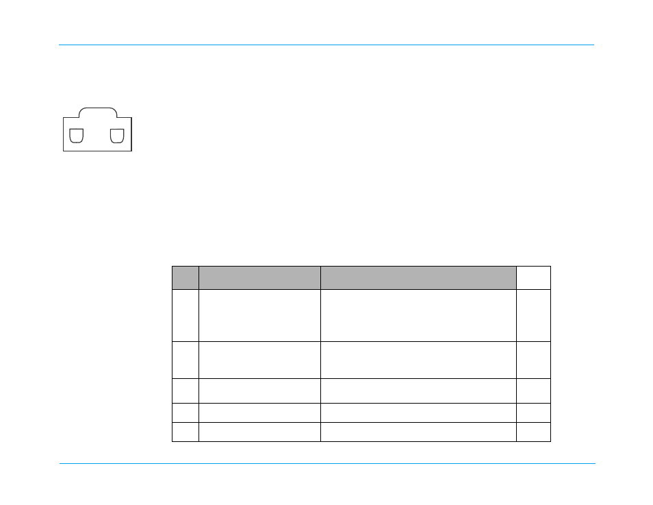
The pacer output can be measured using an oscilloscope set to DC coupling connected across a load resistor. (See
diagram in column for universal cable connector polarity.) The load resistor is a 100 ohm, 5 watt or greater. The pacer
output is a positive going pulse, 40 +/- 2 ms duration with an amplitude of 0.1 volt per milliamp of selected output
(e.g., 40 milliamps of selected output has an amplitude of 4 +/- 0.5 volts the specified tolerance displayed on the
oscilloscope).
If an external non-invasive pacer analyzer is being used, then follow the manufacturer’s guidelines for measuring the
frequency (ppm), output (mA) and the pulse width measured in milliseconds. Note that the analyzer pace load resistor
must be less than 250 ohms.
Test Setup:
Connect the universal cable from the M Series to the QED 6 Defibrillator Analyzer.
?
Do this...
Verify that...
Pass/
Fail
16.1
Turn the Main Selector knob of
the unit to Pacer Mode.Set the
PACER OUTPUT to 14 mA and
disconnect MFC connector from
the QED 6 analyzer.
The unit displays the CHECK PADS and POOR PAD
CONTACT messages displays, and the pace alarm is
active.
o
o
16.2
Reconnect the
universal cable to
the
QED 6 analyzer. Press Clear
Pace Alarm softkey.
CHECK PADS and POOR PAD CONTACT message
disappears. The pace alarm is cleared.
o
o
16.3
Set rate to 180 ppm; output to
0mA.
No output appears on the QED 6 analyzer.
o
o
16.4
Increase the output to 40mA.
Output on the QED 6 analyzer is 40mA +/- 5mA.
o
o
16.5
Increase the output to 120mA.
Output on the QED 6 analyzer is 120mA +/- 6mA.
o
o