Appendix additional error – Atec Agilent-16047A User Manual
Page 95
The equation for the test fixture’s additional error is shown below:
Ze = ± { A + (Zs/Zx + Yo•Zx)
×
100} (%)
De = Ze/100 (D
≤
0.1)
Ze
: Additional Error for Impedance (%)
De
: Additional Error for Dissipation Factor
A
: Test Fixture’s Proportional Error (%)
Zs/Zx
×
100 : Short Offset Error (%)
Yo•Zx
×
100 : Open Offset Error (%)
Zs
: Test Fixture’s short Repeatability (
Ω
)
Yo
: Test Fixture’s open Repeatability (S)
Zx
: Measured Impedance Value of DUT(
Ω
)
Proportional error, open and short repeatability are mentioned in the test fixture’s operational manu-
al and in this accessory guide. By inputting the measurement impedance and frequency (proportional
error, open and short repeatability are usually a function of frequency) into the above equation, the
fixture’s additional error can be calculated.
Proportional Error:
The term, proportional error (A), was derived from the error factor, which causes the absolute imped-
ance error to be proportional to the impedance being measured. If only the first term is taken out of
the above equation and multiplied by Zx, then
∆
Z = A•Zx (
Ω
). This means that the absolute value of
the impedance error will always be A times the measured impedance. The largeness of proportional
error is dependent upon how complicated the test fixture’s construction is. Conceptually, it is depen-
dent upon the stability of each element of the fixture’s equivalent circuit model. From previous expe-
rience, proportional error is proportional to the frequency squared.
Short Offset Error:
The term, Zs/Zx
×
100, is called short offset error. If Zx is multiplied to this term, then
∆
Z = Zs (
Ω
). It
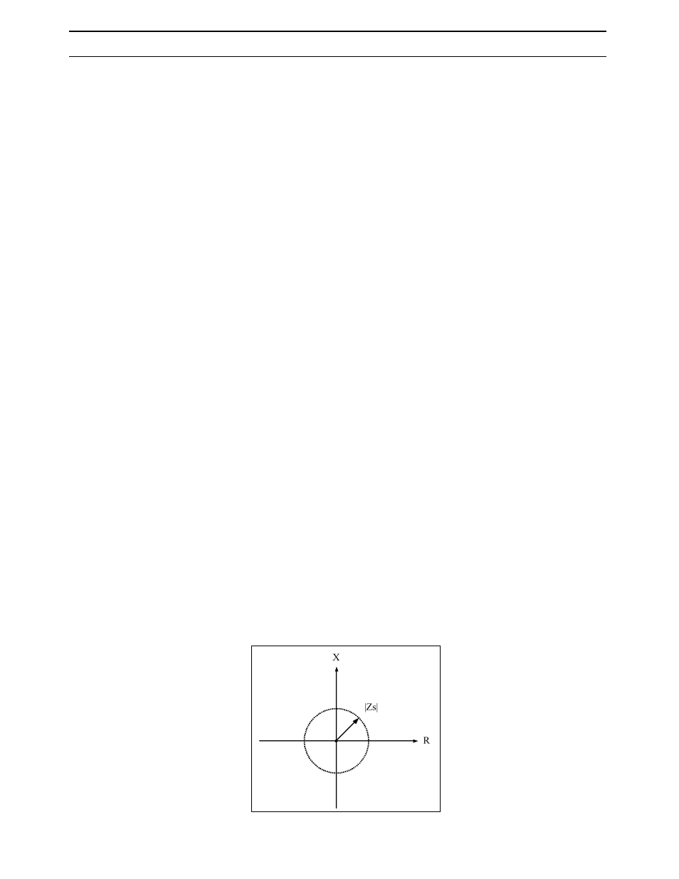
can be concluded that this term affects the absolute impedance error, by adding an offset. Short
repeatability (Zs) is determined from the variations in multiple measurements of the test fixture in
short condition. After performing short compensation, the measured values of the short condition will
distribute around 0 in the complex impedance plane. The maximum value of the impedance vector is
defined as short repeatability. This is shown in the figure below. The larger short repeatability is the
more difficult it is to measure small impedance values. For example, if the test fixture’s short
repeatability is 100 m
Ω
, then the additional error of an impedance measurement under 100 m
Ω
will
be more than 100%. In essence, short repeatability is made up of a resistance and an inductance part,
which become larger as the frequency becomes higher.
Definition of short repeatability
90
Appendix
Additional Error