Up to 3 ghz (7 mm) smd – Atec Agilent-16047A User Manual
Page 59
54
Up to 3 GHz (7 mm)
SMD
Options:
16194A-010: Add EIA/EIAJ industrial standard sized
shorting bar set
16194A-701: Add general sized shorting bar set
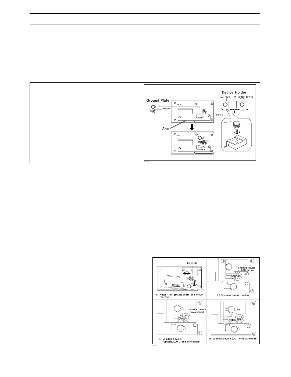
Compensation and Measurement: Before beginning
the measurement, the appropriate device holder (for a
SMD or lead component) must be prepared with the text
fixture. The following figure shows how the device holder
is exchanged to match the device type.
The next step is to perform open and short compensations
in combination with the electrical length compensation.
When measuring above 500 MHz, load copensation is also
recommended. The fixture’s electrical length must be
entered into the electrical length compensation function of
the measurement instrument first. Then open compensa-
tion is performed by separating the high and the low elec-
trodes from each other. The separation should be equiva-
lent in size to the DUT’s width. Short compensation is
performed by using the option 16194A-010/701 shorting
bar set. Load compensation is performed by using the
furnished 50
Ω
SMD chip resistor. After performing open,
short, and load compensations in combination with the
electrical length compensation, the DUT is inserted into
the test fixture. The following figures show how measure-
ment is performed.
Exchanging the device holder
1. Remove the ground plate
2. When measuring SMD, attach
the knob on the device holder.
3. Select the device holder suitable
for the device type. Loosen its
knob and insert into the arm.
4. Set the ground plate.
Placing the device