Up to 110 mhz (4-terminal pair), Lead components – Atec Agilent-16047A User Manual
Page 17
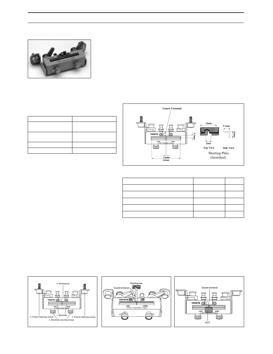
16047E Test Fixture
Terminal Connector: 4-Terminal Pair, BNC
DUT Connection: 2-Terminal
Dimensions (approx.):
135 (W) x 40 (H) x 65 (D) [mm]
Weight (approx.): 200 g
Additional Error:
f: [MHz]
12
Up to 110 MHz (4-Terminal Pair)
Lead Components
Test fixture overview
Connecting a shorting plate
Measuring 3-Terminal device
Description: This test fixture is designed for impedance
evaluation of lead type devices up to 110 MHz. A guard
terminal is available for three terminal devices and a
shorting plate comes secured on this fixture.
Applicable Instruments: 4263B, 4268A, 4279A, 4284A,
4285A, 4288A, 4294A, (4192A, 4194A, 4263A, 4278A)*
* denotes the instrument is obsolete.
Frequency: DC to 110 MHz
Maximum Voltage: ±42 V peak max.(AC+DC)
Operating Temperature: 0°C to 55°C
DUT Size: See figure below with 16047E’s electrode size.
Furnished Accessories:
Compensation and Measurement: Open and short
compensations are recommended before measurement.
Short compensation is performed by shorting the contacts
of the test fixture with a shorting plate. After performing
open and short compensations, the DUT is connected to
the test fixture. The following figures show how
compensation and measurement are performed.
Type of Error
Impedance
Proportional Error
f <
= 15 MHz
0.2 x (f/10)
2
[%]
Proportional Error
f > 15 MHz
4 x (f/100)[%]
Open Repeatability
2 n+10 µ x (f/100) [S]
Short Repeatability
2 m+600 m x (f/100) [
Ω
]
Description
P/N
Qty.
Angle(right-side)
NA
1
Angle(left-side)
NA
1
Screws
0515-0914
4
Shorting Plate
16047-00621
1
Operation and Service Manual
16047-90040
1