Up to 110 mhz (4-terminal pair), Lead components – Atec Agilent-16047A User Manual
Page 18
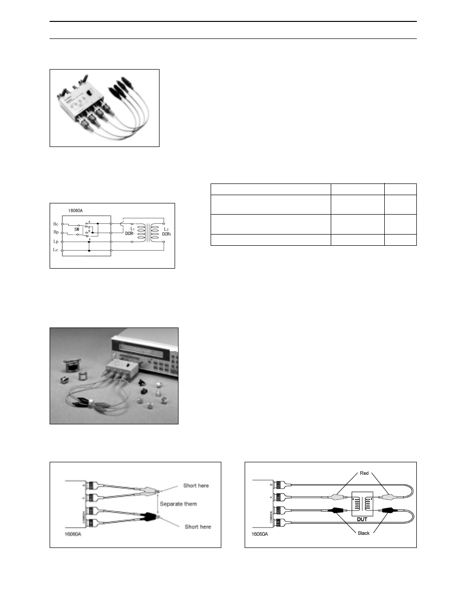
16060A Transformer Test Fixture
Terminal Connector: 4-Terminal Pair, BNC
DUT Connection:
2-Terminal for L measurement
3-Terminal for N, M measurement
See figure below for more information.
Dimensions (approx.):
90 (W) x 35 (H) x 90 (D) [mm]
Cable Length (approx.): 25cm
Weight (approx.): 300 g
Additional Error: The additional error is negligible when
compared to the instrument’s accuracy.
13
Up to 110 MHz (4-Terminal Pair)
Lead Components
Description: This test fixture provides a convenient
means of measuring a transformer’s self-inductance,
mutual inductance, turns-ratio, and dc resistance in the
frequency range of dc to 100 kHz, as appropriate for each
measurement.
Applicable Instruments: 4263A*/B (with Option 4263B-
001) Only
Frequency: DC to 100 kHz
Operating Temperature: 0°C to 55°C
DUT Size: The lead wire of the transformer should not
have a diameter greater than 4 mm, otherwise the alliga-
tor clip will not be able to clamp onto it properly.
Furnished Accessories:
Compensation and Measurement: Open compensation
is recommended before measurement. Open compensation
is performed by connecting the alligator clips of “A” and “B”
terminals together and separating them from the likewise
connected alligator clips of the COMMON terminals.
After performing open compensation, the transformer is
connected to the test fixture. The “A” and “B” terminals
are connected to the high terminals of the transformer.
The COMMON terminals are connected to the low
terminals of the transformer. The following figures show
how compensation and measurement are performed.
Open compensation
Connecting a transformer
Description
P/N
Qty.
Test Leads (black), Alligator clip
to BNC(m)
16060-61601
2
Test Leads (red), Alligator clip
to BNC(m)
16060-61602
2
Operation and Service Manual
16060-90000
1
4263B with 16060A