Bnc inputs 1 through 4, Virtual inputs (inputs 5 through 19), Mgp pro series • installation 7 – Extron Electronics MGP Pro Series User Guide User Manual
Page 13
MGP Pro Series • Installation
7
A
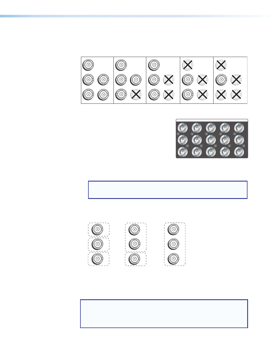
BNC inputs 1 through 4 — Plug RGB, high or standard definition component video,
S-video, or composite video sources into these fully configurable BNC connectors, as
shown in figure 4. Configure these connectors for the desired signal types via the front
panel, the Windows-based control software, SIS commands, or the MGP web pages.
RGBHV
Video
RGsB or
Component
Video
S-video
Composite
Video
RGBS or
RGBcvS
Video
H
/HV
V
R
/R-Y
G
/Y
VID
B
/C
B-Y
H/HV
B/C
B-Y
H
/HV
V
R
/R-Y
G
/Y
VID
B
/C
B-Y
V
R/R-Y
G/Y
VID
B
/C
B-Y
H/HV
V
R/R-Y
G/
Y
VID
B
/C
B-Y
H/HV
V
R/R-Y
G/Y
VID
1
1
1
1
1
Figure 4.
Connecting to RGB, HD Component Video, S-video, or Composite
Video Inputs 1 through 4
B
Virtual inputs (inputs 5 through 19) —
Connect standard definition component video,
S-video, or composite video sources to these
BNC connectors. The 15 BNC connectors for the
virtual inputs are arranged in columns of three.
In each column, you can connect inputs as
follows (see figure 5):
•
Up to three composite video inputs (can be plugged into any connector or
connectors in the column)
•
One S-video input and, optionally, one composite video input
NOTE: The S-video must always be connected to the top two BNC
connectors. The Y connector must be on top, the C connector in the middle.
A composite video source can be connected to the bottom BNC connector.
•
One interlaced component video source (must be connected to all three BNC
connectors in the column).
VID
Y
VID
B-Y
C
VID
R-Y
5
6
7
VID
Y
VID
B-Y
C
VID
R-Y
5
6
7
S-video and Composite
Component
VID
Y
VID
B-Y
C
VID
R-Y
5
6
7
Composite
Figure 5.
Virtual Input Connection Examples
You can configure these virtual inputs for the desired signal types using the MGP Series
Control Program (see the control software help file) or SIS commands (see the
section beginning on page 42. They cannot be configured
via the front panel.
NOTE: When you configure a virtual input as S-video (using two input connectors)
or component video (using three input connectors), pressing any one of its
equivalent buttons selects the input. For example, if you plug an S-video source
into input connectors 8 and 9, pressing either the 8 or the 9 input button selects
that input.
5
6
7
VID
Y
VID
B-Y
C
VID
R-Y
8
9
10
VID
Y
VID
B-Y
C
VID
R-Y
11
12
13
VID
Y
VID
B-Y
C
VID
R-Y
14
15
16
VID
Y
VID
B-Y
C
VID
R-Y
17
18
19
VID
Y
VID
B-Y
C
VID
R-Y
VIRTUAL INPUTS