Extron Electronics IN1608 MA User Guide User Manual
Page 16
IN1606 and IN1608 Series Scaling Presentation Switcher • Installation
10
e
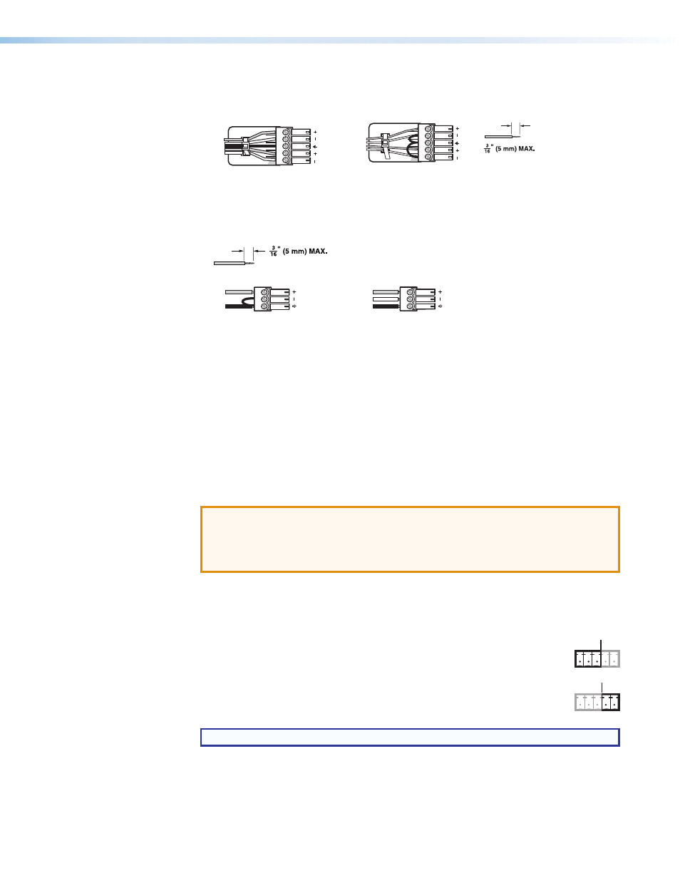
Analog audio input connectors — Connect audio sources to the 5-pole captive
screw connectors associated with the desired input. Wire the connector for line level,
balanced or unbalanced, analog stereo.
Unbalanced Audio Input
Balanced Audio Input
Tip
Ring
Tip
Ring
Sleeves
Tip
Sleeve
Sleeve
Tip
LR
LR
Do not tin the wires!
Figure 6.
Audio Input Connector Wiring
f
Mic/line connectors — Connect unbalanced audio sources to the 3-pole captive
screw connectors for configurable MIC or LINE level inputs.
Balanced Mic Input
Unbalanced Mic Input
Tip
Ring
Tip
Sleeve
Sleeve
Do not tin the wires!
Figure 7.
Mic/Line Connector Wiring
g
DTP output connector (IN1608 models only) — Connect a DTP 230 receiver to
the DTP Out RJ-45 connector to send all signals over a single twisted pair cable (see
Twisted Pair Recommendations for DTP Communication
and cable recommendations). This connection supports the following:
•
HDCP-compliant digital video
•
Re-embedded program audio into the TMDS output or analog audio
•
DTP standard RS-232 and IR pass-through signals on associated 5-pole captive
screw connectors.
•
Remote power to DTP 230 receiver
ATTENTION:
•
Do not connect this connector to a computer or telecommunications network.
•
DTP remote power is intended for indoor use only. No part of the network that
uses DTP remote power should be routed outdoors.
Signal LED — Lights when the scaler is receiving an active video signal from a DTP
transmitter.
Link LED — Lights when a valid link is established to a DTP transmitter.
RS-232 Over DTP port — To pass bidirectional serial control between
DTP-compatible devices, connect a control device to the 5-pole captive
screw connector. This port includes only the 3 poles labeled “RS-232.”
IR Over DTP port — To transmit and receive IR signals, connect a control
device to the 5-pole captive screw connector. This port includes only the
2 poles labeled “IR” and shares the ground pole with the RS-232 port.
NOTE: RS-232 and IR data can be transmitted simultaneously.
h
Amplified audio output connector (IN1608 SA and IN1608 MA models only) —
Connect speakers to the 4-pole or 2-pole captive screw connector.
IR
Tx Rx G
Tx Rx
RS-232
IR
Tx Rx G
Tx Rx
RS-232