H-5223 – Xylem H-5223 User Manual
Page 19
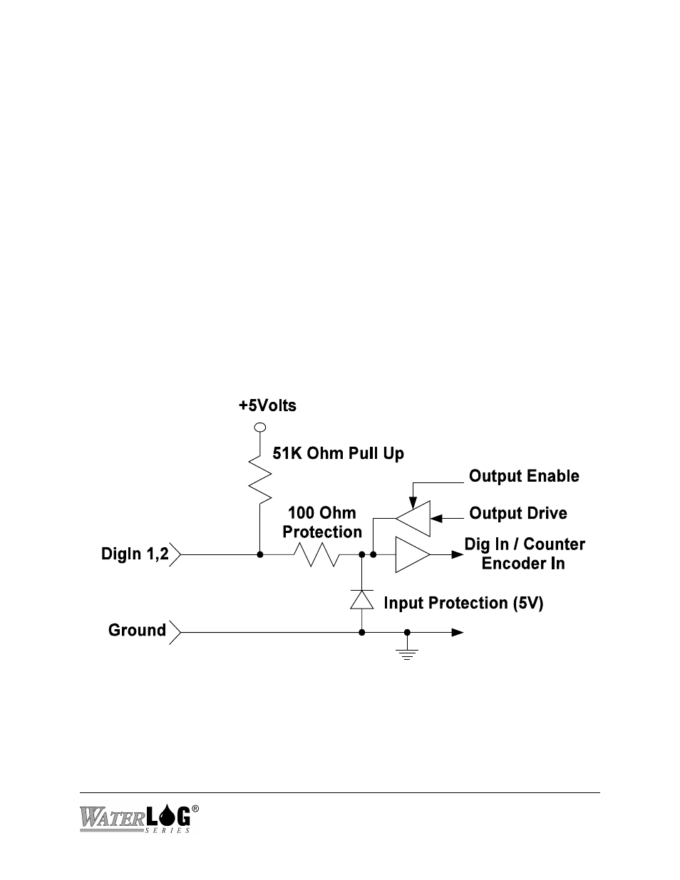
Figure 2-5 Digital I/O Counter Input
2.2.4 Digital I/O 1 and 2
Pins 9 and 10 of the terminal block provide connection points for the two digital I/O signals.
Notice pin 8 is a digital ground and is grouped with these two pins. When using the digital I/O’s
this ground pin should be used as the reference point. Do not use the analog grounds.
The two digital I/O signals can be configured independently as inputs or as outputs. In the input
mode, the signal has an internal pull up resistor of 51K Ohms. This allows a switch closure to
ground to activate the input. It can also be driven using 5.0 volt logic levels. As an output, the
drive capability is limited by a 100 Ohm protection resistor. The output will still be about 4.0
volts or higher with a 10.0 mA or less load. Transient protection is provided for this input to
prevent damage from static discharge or over voltage conditions. When both pins are configured
as inputs, they may be used as a quadrature shaft encoder input. Typical applications for these
digital I/O pins include tipping bucket counter inputs, on / off status inputs, output alarming,
triggering samplers, etc. Figure 2-3 shows a simplified schematic of how these pins are
configured.
H-5223
Hardware Options and Installation 2-5