8 quick access – Bell & Gossett 10 001 265R5 TechnoForce Pump Controller User Manual
Page 51
TECHNOFORCE Installation, Operation, and Maintenance
45
Operation
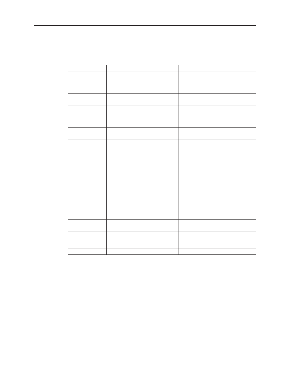
To view possible causes for alarm/event, press the
HELP key again after the alarm/event is displayed. Refer to
table below for an overview of the possible alarm/event and their respective causes.
Press the
CLEAR key to return to the main screen. After addressing the source of the alarm/event, press
RESET to re-start the system and/or clear the alarm/event.
The controller logs alarm/event as they occur to aid in troubleshooting unobserved alarm/event. Refer to
Section 6.14.0 for alarm/event logging information
Help Screen Alarm Help/Help Screen Display
Detailed Description
VFD
Failure
“Check
communication
wiring,
and
VFD
display”
High Level
“Check setting of level switch”
High Suction
“Check setting of the HIGH
SUCTION switch” or high suction
settings in the ALARM/EVENTS
set up
High System
“Check system pressure –
manual RESET required”
Low System
“Check system pressure”
Low Suction
“Check setting of the low suction
switch” or low suction settings in the
ALARM/EVENTS set up
Low Level
“Check setting of level switch”
NFSD
“System will restart automatically
when flow occurs”
Pump Fail
“Check DP switch, impeller, coupler,
motor”
Sensor Fail
“Check wiring, piping, polarity,
continuity”
Sensor Reading
“Check wiring of both sensors, and
Drift
compare the pressure reading of both
sensors with pressure gauge ”
Low Battery
Replace OIP battery
Replace OIP battery
The controller is not receiving a closed run
signal from VFD number X after it has been
given a start command or communication
failure or VFD fault
Check for open or closed contacts, refer to
wire diagram for proper connection.
Check for open or closed contacts and high
suction settings, refer to wire diagram for
proper connection
Check the pressure setting in the setup
menu.
Check the pressure setting in the setup
menu.
Check for open or closed contacts and low
suction settings, refer to wire diagram for
proper connection
Check for open or closed contacts, refer to
wire diagram for proper connection.
Check the Reset PSI Drop value and the
pressure sensor connections, refer to the
wire diagram.
The controller is receiving a closed signal
from the differential pressure switch for
pump number X after it has been given a
start command
The controller is not receiving the proper
4-20mA
“Check wiring of both sensors, and compare
the pressure reading of both sensors with
pressure gauge ”
5.8 Quick Access
Using quick access function user can directly jump to the setup screen need to be setup. To use this function
press
QUICK ACCESS/6 key from status screen. The display now shows.
Enter Page ####
Exit $ (Y/N)
Press
NO/0 to edit the page number. Enter the screen number need to be access and press the ENTER key.
It will lead to the setup screen entered. Refer the appendix for the quick access screen numbers.