4 main parts and functions – Bell & Gossett 10 001 265R5 TechnoForce Pump Controller User Manual
Page 13
TECHNOFORCE Installation, Operation, and Maintenance
7
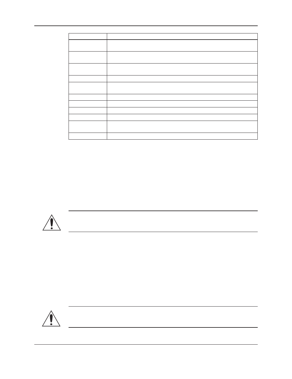
Nameplate Data
Explanation
Model Number
The manufacturer’s number to indicate the particular type of product which
has been acquired.
Serial Number
A set of characters that uniquely identifies a single unit and can be used for
traceability and warranty purposes.
Station Voltage
The rated voltage at which the station has been designed for. Should match the
application site supply voltage.
System FLA
The full-load-amperage at which the station can operate.
SCCR
“Short-Circuit Current Rating”. Represents the maximum level of short-circuit
current that a component or assembly can withstand.
Largest Motor HP
The rated HP for the largest Pump in the system.
Station Flow
The designed duty point, in GPM, LPH, etc.
Suction Pressure
The line pressure on the input side of the pump station.
Discharge Pressure The line pressure on the output side of the pump station.
Pump Boost
The difference between the input side of the pump station and the output side
of the pump station.
Date Code
Marking of products to indicate their date of manufacture.
3.4 Main parts and functions
3.4.0 Input voltage
The VFD and TechnoForce Pump Controller can be set up to operate across a broad range of voltages. It was
factory set to operate on the voltage shown on the nameplate. Check the VFD nameplate for the proper input
and output voltages before wiring the VFD.
The voltage tolerance is +10/-5% and phase to phase voltage must not have an imbalance greater than 5 VAC.
3.4.1 Ground connections
A grounding terminal is provided for a dedicated ground wire connection. All provisions of the National Electrical
Code and local codes must be followed.
WARNING:
• Conduit grounds are not adequate. A separate ground wire must be attached to the ground lug provided in
the enclosure to avoid potential safety hazards.
3.4.2 Power wiring
Power wire types and sizes must be selected based upon conformance with the National Electrical Code and all
local codes and restrictions. In addition, only copper (Cu) wire rated for 75°C (minimum) may be used for the
power connections. Refer to the input current as listed on the nameplate affixed to the enclosure door when
sizing wire.
3.4.3 Output/motor disconnect
It is necessary that any device which can disconnect the motor from the output of the VFD be interlocked to the
emergency shutdown circuits of the VFD. This will provide an orderly shutdown if the disconnecting device is
open circuited while the VFD is in operation. Failure to provide this interlock may result in damaged components
due to improper installation.
CAUTION:
• Metal filings can create electrical short circuits. Do not drill, saw, file or perform any operation
on the VFD conduit entry plate while attached to the VFD.
Product Description