8 leds, 9 i/o – Bell & Gossett 10 001 265R5 TechnoForce Pump Controller User Manual
Page 20
TECHNOFORCE Installation, Operation, and Maintenance
14
Installation
4.8 LEDs
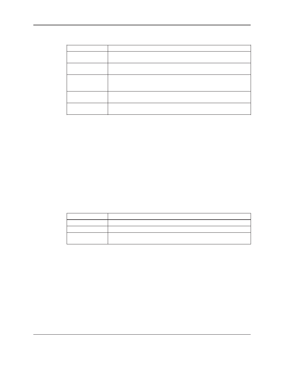
Table 2 gives the meaning of the LED states.
LED Description
START/STOP
On
=
Start
Off = Stop
AUTO/
MANUAL
On
=
Auto
Off = Manual
PUMP
1-6 On
=
Pump
On
Off
=
Pump
Disabled
Blink = Pump Ready, Blink Fast = Pump Failed
RESET/
SILENCE
Off
=
OK
Blink = Reset Required
HELP Off
=
OK
Blink = Event/Alarm(press HELP from the status screens to view)
4.9 I/O
4.9.0 Analog Inputs
The TechnoForce Pump Controller is equipped with 4 analog input channels. The analog inputs must provide
a 4-20mA signal. Typically, analog inputs will be powered by the 24V power supply within the panel. For analog
inputs which source their own power, consult factory.
Shielded 22 AWG cable should be installed for all analog input wiring. The shield must be terminated in the
TechnoForce Pump Controller. Do not connect the shield at the other end of the cable! Insulate the shield so
that no electrical connection is made at the other end of the cable. A twisted pair of #22 AWG conductors can
be used in place of shielded cable. The cable length must be limited to 2,500 feet for #22 AWG wire.
4.9.1 Digital Inputs
The TechnoForce Pump Controller is equipped with (12) 24VDC digital input channels. This signal voltage must
be obtained from the 24VDC power supply mounted to the subpanel. It is not recommended that other power
sources be used without factory approval. All digital inputs are automatically assigned based on Table 3. See the
typical wiring diagram in Appendix.
Table 3: Digital Inputs Functionalities
Functionality
DI #
Description
Start/Stop Sw
1
Remote contact can be used to start/stop the system.
DP 1-6
2-7
Differential pressure switches
Optional DI
8-12
User can select the function of optional input in IO setup, see
section 4.10.17.
# 22 AWG cable should be installed for all field wiring to digital inputs.
4.9.2 Digital Output Module
The digital output consists of 1 normally open and 1 normally closed contact for each output rated at 2.5A at
240V. Customer connections are made directly to the terminals mounted on the digital output module. Refer to
section 4.10.17 for relay output setup.