GE Industrial Solutions EntelliGuard TU Trip Units User Manual
Page 89
DEH-4567B
EntelliGuard TU Trip Units: UL/ANSI Models
Appendix C: Modbus Register Map
©2012 General Electric All Rights Reserved
79
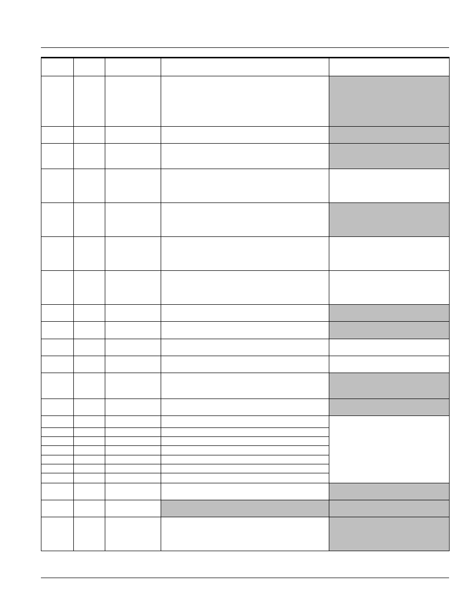
Register
Address
Modicon
Address Variable Name
Allowable Values
Notes
268
40269
Power Reversal
Delay
0 - Off
1- 1
2- 2
3- 3
4- 4
5- 5
6- 6
7- 7
8- 8
9- 9
10- 10
11- 11
12- 12
13- 13
14-14
15-15
269
40270
Power Direction
Setting
0 - Line to Load
1 - Load to Line
270
40271
Power Demand
Interval
1 - 5
2 - 10
3 - 15
4 - 20
5 - 15
..
12 – 60
271
40272
Relay1 (Output1)
Function
1 - Group 1
2 - Group 2
3 - Group 3
4 - Group 4
5 - Group 5
6 - Group 6
7 - Group 7
8 - Group 8
9 - Group 9
10 - Group 10
11 - Group 11
If RELT is optioned, Output 1 will have
Group 7 and it cannot be changed
272
40273
Relay2 (Output2)
Function
1 - Group 1
2 - Group 2
3 - Group 3
4 - Group 4
5 - Group 5
6 - Group 6
7 - Group 7
8 - Group 8
9 - Group 9
10 - Group 10
11 - Group 11
273
40274
Relay3 (Output3)
Function
1 - Group 1
2 - Group 2
3 - Group 3
4 - Group 4
5 - Group 5
6 - Group 6
7 - Group 7
8 - Group 8
9 - Group 9
10 - Group 10
11 - Group 11
GTU 40 Only (IEC Version)
274
40275
Relay4 (Output4)
Function
1 - Group 1
2 - Group 2
3 - Group 3
4 - Group 4
5 - Group 5
6 - Group 6
7 - Group 7
8 - Group 8
9 - Group 9
10 - Group 10
11 - Group 11
GTU 40 Only (IEC Version)
275
40276
Input 1 Function 0 - None
2 - Reduce Instantaneous
3 - Reset Relays
276
40277
Input 2 Function 0 - None
1 - Trip Breaker
2 - NA
3 - Reset Relays
277
40278
Input 3 Function 0 - None
1 - Trip Breaker
2 - NA
3 - Reset Relays
GTU 40 Only (IEC Version)
278
40279
Input 4 Function 0 - None
1 - Trip Breaker
2 - NA
3 - Reset Relays
GTU 40 Only (IEC Version)
285
40286
Waveform
Capture
0 - Disable
1 - Manual
2 - Over Current
3 - Protection
Relays
4 - Current Alarm 1
5 - Current Alarm
2
6 - All
286
40287
Language
0 - English
1 - French
2 - Spanish
3 - German
4 - Chinese
287
40288
Time Sync Year
8 bit
Date and time values are pre-loaded for
some point in the future in registers 287
– 293.
At the date and time entered in those
registers, command 103 is sent to the
device, which updates the device’s
current date/time settings with the new
settings.
288
40289
Time Sync Month 8 bit
289
40290
Time Sync Date
8 bit
290
40291
Time Sync Day
8 bit
291
40292
Time Sync Hour
8 bit
292
40293
Time Sync Minute 8 bit
293
40294
Time Sync Second 8 bit
294
40295
Health status
output type
0 - NC
1 - NO
295
40296
HSI Output
Polarity
296
40297
Current Alarm 1
Pickup On
1 - 0.5
2 - 0.55
3 - 0.60
4 - 0.65
5 - 0.70
6 - 0.75
7 - 0.80
8 - 0.85
9 - 0.90
10 - 0.95
11 - 1.00