Table 28: ground fault pickup settings, Protection type, Sensor, ict – GE Industrial Solutions EntelliGuard TU Trip Units User Manual
Page 23: Ground fault pickup threshold (( ict), Gf sum, Gf sum alarm, Gf ct, Gt ct alarm, Gf/alarm pickup, Ground-fault delay
DEH-4567B
EntelliGuard TU Trip Units: UL/ANSI Models
Protection
©2012 General Electric All Rights Reserved
13
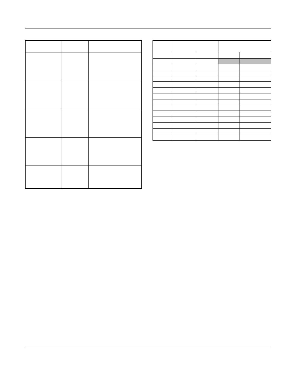
Table 2-8: Ground Fault Pickup Settings
Protection
Type
Sensor, I
CT
Ground Fault Pickup
Threshold (
× I
CT
)
GF SUM
GF SUM ALARM
GF CT
GT CT ALARM
150–2000 0.20–0.60 (max of 1200
A) (increment of 0.01)
with OFF as a selection
when GF or GF Alarm
Switchable is optioned.
GF/ALARM
Pickup
2500-3200 0.20–0.37 (increment of
0.01) with OFF as a
selection when GF or GF
Alarm Switchable is
optioned.
GF/ALARM
Pickup
4000
0.20–0.30 (increment of
0.01 with OFF as a
selection when GF or GF
Alarm Switchable is
optioned.
GF/ALARM
Pickup
5000
0.20–0.24 (increment of
0.01) with OFF as a
selection when GF or GF
Alarm Switchable is
optioned.
GF/ALARM
Pickup
6000
0.2 (1200 A) with OFF as
a selection when GF or
GF Alarm Switchable is
optioned.
Ground-Fault Delay
This function sets the delay before the breaker trips when
the ground-fault pickup current has been detected.
The Ground Fault Delay setting consists of a selection
between two I
2
T slopes: an optional steeper fuse slope, and
fixed delay only. One of fourteen fixed time bands is also
selected. The fixed delay bands are listed in Table 2-9.
The Ground Fault Delay settings consist of two user
settings. The Time Delay band and the Ground Fault
protective function curve shape. The time delay bands
consist of up to 14 definite time response bands. Table 2-8
lists the available time delay bands for the various circuit
breakers. There are four ground fault protective functions
shapes that may be selected. Definite time (OFF), l
2
t slope,
l
4
t slope and a double break special selective ground fault
with dual l
2
t slopes.
The Ground Fault Delay band may be set to off based on
trip unit configuration. Note that “switchable Ground Fault”
is not UL listed.
Table 2-9: Ground Fault Time Delay Bands, 50 Hz & 60 Hz
• Power Break I, Power Break II, WavePro and AKR time band width is 60
msec.
• EntelliGuard G 60 Hz time band width is 0.055 sec.
• EntelliGuard G 50 Hz time band width is 0.060 sec.
ALARMS
Ground Fault Alarms
The Ground Fault alarm DOES NOT issue a trip event. If
tripping on ground fault is required order LSIG not LSIGA.
Instead it can turn on a digital output if an output is
configured for it. It will always turn on an indication in the
Modbus register map. The output can be used to turn on a
light or other signal but it WILL NOT GENERATE A TRIP
EVENT.
All GTUs with a Ground Fault trip can also send a signal
after the trip event that a GF occurred.
Current Alarm
The trip unit provides two current alarms. These alarms will
trigger an alert when current consumption exceeds their
setpoints. This is useful for implementing load shedding
processes, and serves as an alert to impending Long Time
pickup. The alert can be signaled either via
communications or via digital output. The Current Alarms’
ON/OFF pickup settings are 0.5 to 1.0 xIn in steps of 0.05.
The trip unit does not allow the current alarm OFF setpoint
to be set above the ON setpoint.
If the highest measured phase current goes above the
Current Alarm ON setpoint and remains above the setpoint
for more than 60 seconds the alarm will be triggered. If the
current falls below the Current Alarm OFF setpoint for more
than 60 seconds while the Current Alarm is active, the
alarm condition will be cleared.
Time
Band
EntelliGuard G UL
Commit Time (S)
PB I, PB II, WavePro,
AKR Commit Time (S)
60 Hz
50Hz
60 Hz
50Hz
1
0.042
0.050
2
0.058
0.060
0.058
0.060
3
0.092
0.110
0.092
0.110
4
0.117
0.130
0.117
0.130
5
0.158
0.180
0.158
0.180
6
0.183
0.210
0.183
0.210
7
0.217
0.240
0.217
0.240
8
0.350
0.280
0.350
0.280
9
0.417
0.340
0.417
0.340
10
0.517
0.390
0.517
0.390
11
0.617
0.540
0.617
0.540
12
0.717
0.640
0.717
0.640
13
0.817
0.740
0.817
0.740
14
0.917
0.840
0.917
0.840