Trip unit reinstallation, Wavepro circuit breakers, Removal – GE Industrial Solutions EntelliGuard TU Trip Units User Manual
Page 74: Depress the open button to close the racking door, Reinstallation, Akr (225 a to 5000 a frames) circuit breakers, Type 1: push in the lever to release the trip unit, Type 3: push down on the lever, Figure 131: removing the old trip unit, Figure 132: circuit breaker without trip unit
EntelliGuard TU Trip Units: UL/ANSI Models
DEH-4567B
Installation
64
©2012 General Electric All Rights Reserved
Trip Unit Reinstallation
1.
Pull the trip unit locking lever to the right. While holding
the lever, carefully align the connector on the rear of the
trip unit with the connector in the breaker. Press down
on the trip unit while holding it near the battery cover.
When the trip unit is fully seated, slide the locking lever
back to the left.
2.
Reinstall the breaker top cover and tighten the four
#10-32 screws to 32 in-lb.
3.
Replace the trim plate and tighten the four #8-32
screws to 20 in-lb.
WavePro Circuit Breakers
Removal
1.
Open the circuit breaker and remove it from the cubicle
or substructure. Place it on a suitable work surface.
2.
For 800 A, 1600 A and 2000 A frame circuit breakers,
insert the racking handle (catalog number 568B731G1)
and move the racking mechanism to the TEST position,
as shown on the draw-out position indicator.
3.
Depress the OPEN button to close the racking door.
4.
Remove the wire forms and remove the trim plate from
the breaker.
5.
Remove the six ¼ hex head screws, securing the
escutcheon to the breaker (three at top and three at
bottom). Pull the manual-charging handle out part way,
and then slide off the escutcheon.
6.
Pull out the locking side on the right of the trip unit
mounting plate, and then pull the trip unit out carefully
disengaging the pins on the rear connector.
7.
Pull out the locking side on the right of the trip unit
mounting plate, and then pull the trip unit out carefully
disengaging the pins on the rear connector.
Reinstallation
1.
Pull out the locking side on the right of the trip unit
mounting plate. Push the trip unit into place, carefully,
engaging the 50 pin connector and lining up the
rejection posts on the rear of the trip unit with the holes
in the mounting plate. Push the locking slide to the left.
2.
Ensure the breaker racking mechanism is still in the
TEST position. Pull the manual charging handle out
partway, and then slide the handle through the slot in
the escutcheon and move escutcheon into place. Insert
the six mounting screws and tighten to 14-20 in-lb.
3.
Replace the trim plate around the escutcheon by re-
hooking the wire forms into the sides.
4.
Insert the racking handle and return the racking
mechanism to the DISC position, as shown by the draw-
out position indicator.
5.
Reinstall the circuit breaker into its cubical or
substructure.
AKR (225 A to 5000 A Frames) Circuit Breakers
1.
Open the circuit breaker by pressing the red TRIP button
on the front of the breaker escutcheon.
2.
Disconnect any secondary wire harnesses between the
breaker and the switchgear.
3.
On draw-out breakers, rack the breaker all the way out
to the DISCONNECT position.
4.
Follow the instructions on the label attached to the
PROGRAMMER RELEASE LEVER to remove the trip unit.
There are three types of mounting plates:
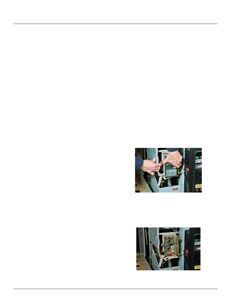
• Type 1: Push in the lever to release the trip unit
• Type 2: Pull out the lever to release the trip unit as
shown in Figure 13-1
• Type 3: Push down on the lever
Figure 13-1: Removing the Old Trip Unit
5.
If the breaker is equipped with a MicroVersaTrip® 9 trip
unit, the 36-pin trip unit connector must be removed
and remounted on the adapter bracket provided. Slide
the connector out of the mounting plate and install it on
the adapter bracket, as shown in Figure 13-2.
Figure 13-2: Circuit Breaker without Trip Unit