Section 3. setting up the trip unit, Setup navigation, Notice – GE Industrial Solutions EntelliGuard TU Trip Units User Manual
Page 32: Long time pickup, Long time delay, The gtu has two lt band options, Short time pickup, Short time delay, See des-092 and des-097 for delay band information
EntelliGuard TU Trip Units: UL/ANSI Models
DEH-4567B
Setting up the Trip Unit
22
©2012 General Electric All Rights Reserved
SECTION 3.
SETTING UP THE TRIP UNIT
SETUP NAVIGATION
Use the LEFT and RIGHT arrows to
navigate from screen to screen
and to specific items — Pickup,
Band, etc.
Use the UP and DOWN arrows to
adjust setpoint item values. For
example, pickup ranges from 0.50
to 1.00.
NOTICE
Until you hit the middle ENTER key the
setting will not save.
If you try to ENTER and it says LOCKED, you must enter the
password. See “Password Setup“ in SECTION 3 for more
information.
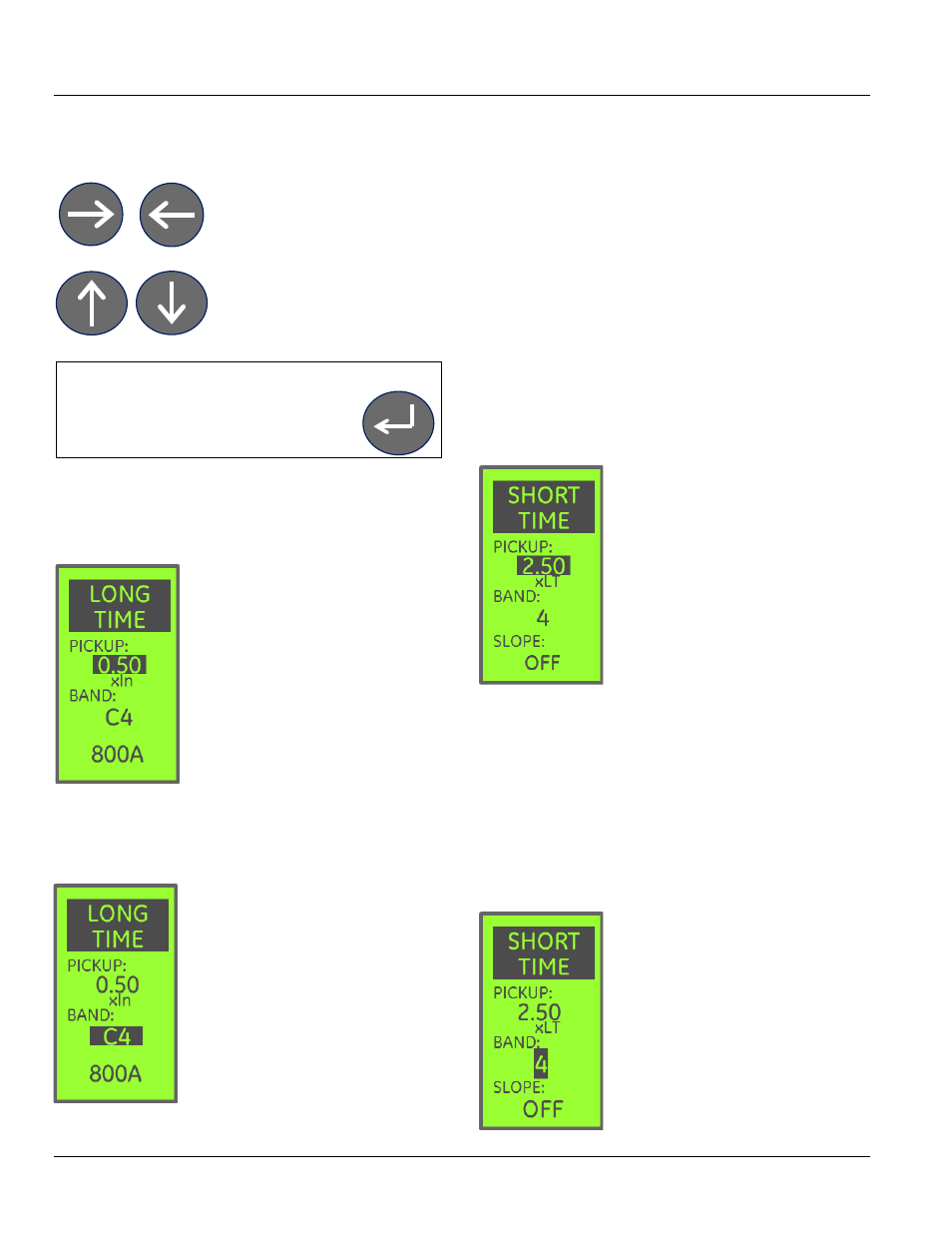
LONG TIME PICKUP
Long Time Pickup defines the
threshold where the LT element
begins to “timeout” toward tripping as
a percentage of the Rating Plug
current (In). The actual pickup
threshold, in amperes, is indicated at
the bottom of the screen
The LT pickup adjustment range is
between 50% (0.50) and 100% (1.0) of
the rating plug.
What this shows:
The Pickup setpoint is highlighted and set to 50%. This is a
1600A breaker, since the indicated pickup threshold is
800A (50% of 1600A = 800A)
LONG TIME DELAY
Long Time Band selects the “delay
band” for the LT element, or how long
the trip unit will allow an overload to
persist before the breaker is
commanded to open.
The GTU has two LT band options:
• I
2
t – the standard set of delay
bands, included in every GTU.
• I
4
t – also called “fuse bands” – are
now also standard (on trip unit models
starting with “J”).
See DES-095 for i
2
t and DES-096 for i
4
t trip time curve
information for EntelliGuard G. See DES-095 and DES-096
for Wavepro, AKR, and Power Break applications.
The I
2
t band is adjustable from C MIN to a maximum that
varies by circuit breaker application.
The I
4
t band (
when installed
) is adjustable from F MIN to F
MAX.
The I
4
t and I
2
t selections are both included in the Band
setpoint – continue scrolling past the min or max I
2
t setting
values to reach the I
4
t (fuse) band setpoints.
What this shows:
The C4 i
2
t delay band is currently selected.
Tip: You can navigate completely through the entire range
of settings using just the UP or DOWN arrow.
SHORT TIME PICKUP
Short Time Pickup defines the
threshold where the ST element
begins to “timeout” toward tripping,
as a multiple of the Long Time Pickup
threshold.
If Long Time Pickup is set to 800A, and
Short Time Pickup is set to 2.5, ST will
go into pickup when the current
exceeds 2000A.
Short Time is an optional element. If
ST is not installed in your trip unit, this
screen will not appear.
The ST pickup adjustment range is between 1.5 and a
maximum that is breaker dependent. Check DES-092 and
DES-097 as well as “Short Time Protection,” above, for
pickup threshold limits.
What this shows:
The Pickup setpoint is highlighted and set to 2.5 x the LT
pickup value.
SHORT TIME DELAY
Short Time Band selects the “delay band” for the ST
element, or how long the trip unit will
allow an overload to persist before the
breaker is commanded to open.
See DES-092 and DES-097 for delay
band information.
The band is adjustable from 1.5 to a
maximum that varies by circuit
breaker application.
If the switchable option is available, ST
can be disabled by selecting OFF as