Section 8. serial communication, Pin 2: modbus rx, Pin 3: modbus tx – GE Industrial Solutions EntelliGuard TU Trip Units User Manual
Page 58: Pin 6: +24vdc, Pin 8: 24v return, Modbus rtu, Modbus address setting, Modbus baud rate and port configuration, 1200-8n2, 1200-8o1
EntelliGuard TU Trip Units: UL/ANSI Models
DEH-4567B
Serial Communication
48
©2012 General Electric All Rights Reserved
SECTION 8.
SERIAL COMMUNICATION
The EntelliGuard Trip Unit offers Modbus RTU or Profibus DP
over RS-485 optionally, via terminals on the circuit
breaker’s secondary disconnect. Modbus RTU over RS-232
is always available via the front panel 15 pin Test Kit D-
connector. To use the RS232 Port in the front, the GTUTK20
Trip Unit Test Kit is recommended. The Test Kit supplies
convenient connections to computer serial ports and the
24VDC required for communication.
If a GTUTK20 test kit is not available you can create your
own test kit communications cable, using the following pin
assignments:
• Pin 2: Modbus RX
• Pin 3: Modbus TX
• Pin 6: +24VDC
• Pin 8: 24V Return
It is also possible to provide power to the trip unit through
the secondary disconnect on breakers so equipped,
eliminating the need to supply 24V through the test kit port.
Connection to computers lacking a 9 pin serial port may be
done reliably through a USB-to-serial converter readily
available at most office supply stores.
MODBUS RTU
Modbus is a master-slave protocol where a single host or
master device initiates and controls all communication
with the other devices (or slaves) on the network. The
hardware interface is implemented as duplex two-wire RS-
485, where data are transmitted and received in separate
time slices. Per the EIA-485 standard the number of
devices that can be connected on a single communication
port is limited to 32 (including the
master).
Please refer to the EIA-485
standard for complete details of
the physical interface including cabling, termination, and
shielding.
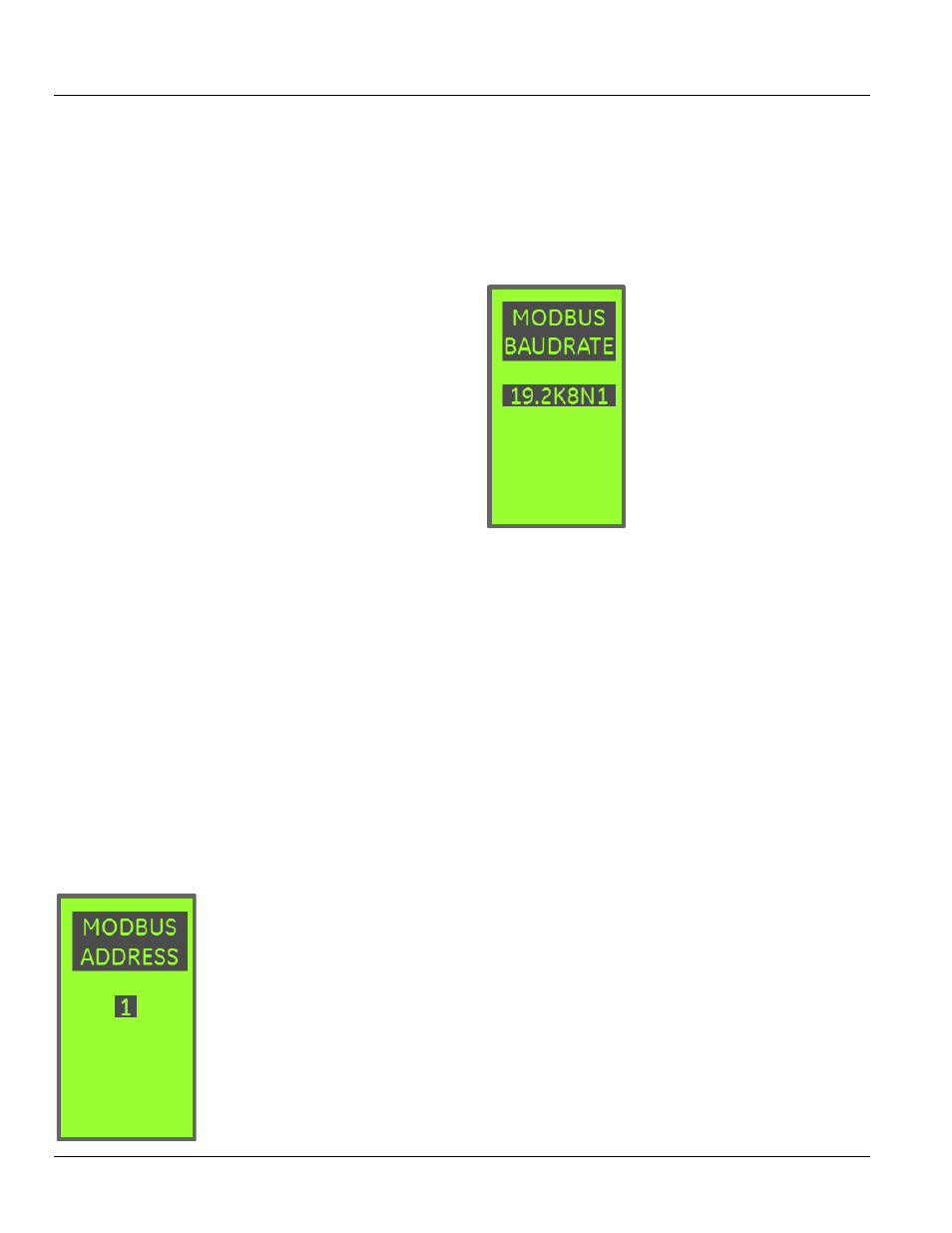
Modbus Address Setting
In a Modbus RTU Network, each
EntelliGuard Trip Unit module must
have a unique address that can be
set from 1 to 247. Addresses do
not have to be sequential, but no
two units can have the same
address.
Generally, each
unit added to the
link uses the next higher address,
starting at 1. The Modbus slave
address can be set using the keypad.
The Modbus slave address configuration can be set using
the LCD keypad, or over Modbus
communications.
For LCD
configuration, navigate to the Modbus Settings
window under the SETUP main menu item. Use the up and
down arrows to set the address to the desired value.
Modbus Baud Rate and Port Configuration
The EntelliGuard G Trip Unit
supports the configured baud rate
settings listed below, which can
be set using the keypad. The
Modbus Communications
parameter setting screen is
shown In Illustration to the left.
The EntelliGuard Trip Unit
supports the configured baud rate
settings listed below, which can
be set via keypad. The first
number is the baud rate (300–
19,200), the first digit after the
dash is the number of data bits
(fixed at 8), the letter represents the parity setting (N =
none, E = even, O = odd), and the last digit is the stop bit.
• 300-8N2
• 300-8O1
• 300-8E1
• 300-8N1
• 600-8N2
• 600-8O1
• 600-8E1
• 600-8N1
• 1200-8N2
• 1200-8O1
• 1200-8E1
• 1200-8N1
• 2400-8N2
• 2400-8O1
• 2400-8E1
• 2400-8N1
• 4800-8N2
• 4800-801
• 4800-8E1
• 4800-8N1
• 9600-8N2
• 9600-801
• 9600-8E1
• 9600-8N1
• 19200-8N2
• 19200-8O1
• 19200-8E1
• 19200-8N1