Dc power is removed from the trip unit, Modbus command 112 off is sent to the trip unit, Output relay – group 4 and 5 – GE Industrial Solutions EntelliGuard TU Trip Units User Manual
Page 40: Output relay – group 6, Output relay – group 7, Output relay –group 8
EntelliGuard TU Trip Units: UL/ANSI Models
DEH-4567B
Setting up the Trip Unit
30
©2012 General Electric All Rights Reserved
1.
If a Protective Relay Tripping element operates, the
Output Relay is latched on.
2.
If the Protective Relay drops out of pickup, the Output
Relay will remain latched.
3.
The Output Relay will remain latched after the
Protective Relay drops out until one of the following
occurs:
• DC power is removed from the trip unit.
• The RESET RELAYS command is issued from the
STATUS menu on the trip unit LCD. Reset is
accomplished by pressing the ENTER button from
that screen.
• Modbus command 112 OFF is sent to the trip unit.
• An Input has been mapped to the “Reset Relays”
function, and is activated.
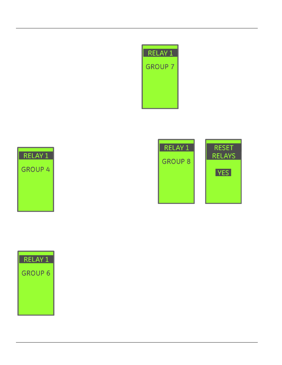
OUTPUT RELAY – GROUP 4 AND 5
Output Relay configurations Group 4
and Group 5 link the relay to the
Current Alarm 1 and Current Alarm 2
element, respectively.
1.
If the associated Current Alarm
goes into pickup, the Output Relay is
turned on.
2.
The Output Relay drops out when
the associated Current Alarm drops
out of pickup, or if DC power is
removed.
3.
The Output Relay cannot be reset by LCD command as
long as the Current Alarm is in pickup.
4.
The Output Relay cannot be reset over Modbus as long
as the Current Alarm is in pickup.
OUTPUT RELAY – GROUP 6
Output Relay Configuration Group 6
links the output relay to the Error
status of the trip unit. Any internal
error condition that results in a
display on the Error Status screen will
set this output. The output does not
latch – it remains energized as long
as the error condition persists.
OUTPUT RELAY – GROUP 7
Output Relay configuration Group 7
links the relay to the Reduced Energy
Let Through (RELT) function.
Whenever RELT is engaged the output
relay will be closed.
The RELAY cannot be reset from the
LCD or via communications while
RELT is active.
When the RELT command is removed,
RELT remains in force for 10-15
seconds. The Output Relay remains
closed during this time as well.
Relay 1 is automatically and permanently assigned Group 7
on any trip unit with the RELT option installed.
OUTPUT RELAY –GROUP 8
Output Relay configuration Group 8 (ALARM and TRIP) links
the relay to the GF Sum Alarm, GF Sum Trip, GF CT Alarm,
and GF CT Trip protection functions.
1.
If the GF Sum or GF CT Tripping elements operate, the
Output Relay is latched on.
2.
The Output Relay will not drop out if the tripping
element falls out of pickup.
3.
The Output Relay will remain latched after the tripping
element drops out of pickup until one of the following
occurs:
• DC power is removed from the trip unit.
• The RESET RELAYS command is issued from the
STATUS menu on the trip unit LCD. Reset is
accomplished by pressing the ENTER button from
that screen.
• Modbus command 112 OFF is sent to the trip unit.
• An Input has been mapped to the “Reset Relays”
function, and is activated.