Modbus function codes, Read holding registers, Read input registers – GE Industrial Solutions EntelliGuard TU Trip Units User Manual
Page 59: Force single coil, Preset single register, Preset multiple registers, Read general reference, Modbus network configuration, Pull-up resistor to 5 v on the positive line, Pull-down resistor to common on the negative line
DEH-4567B
EntelliGuard TU Trip Units: UL/ANSI Models
Serial Communication
©2012 General Electric All Rights Reserved
49
Modbus Function Codes
The EntelliGuard Trip Unit supports the following function
codes:
•
03: Read
Holding Registers
• 04: Read Input Registers
• 05: Force Single Coil
• 06: Preset Single Register
• 16: Preset Multiple Registers
• 20: Read General
Reference
Modbus Network Configuration
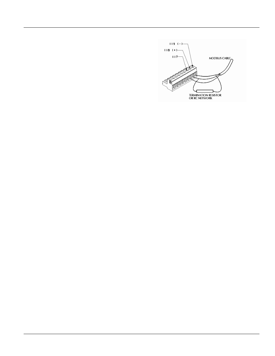
Figure 8-1 illustrates the standard two-wire Modbus
topology. To minimize the effects of reflections from the
ends of the RS-485 cable caused by impedance
discontinuities in the system, a line-terminating RC network
must be placed at each end of the bus, as illustrated in
Figure 8-1. The simplest solution is to connect the
terminator at the communication terminals of the devices
at each end of the bus.
In most cases, pull up and pull down resistors are not
required.
If one or more connected devices require
polarization, or if the master device does not provide
proper polarization, then a pair of resistors must be
attached to the RS-485 balanced wire pair, as follows:
• Pull-up resistor to 5 V on the positive line
• Pull-down resistor to common on the negative line
These resistors must be between 450
Ω and 650 Ω, and are
selected based on the maximum current flow permitted by
the connected devices. The latter may allow a higher
number of devices to be connected to the serial bus.
RS-232 and RS-485 Connections
On the front panel of the EntelliGuard Trip Unit is a 15-pin
connector for the RS-232 Modbus connection. This
connector mates with a cable supplied with the GTUTK20
Digital Test
Kit.
If the trip unit and circuit breaker are equ
ipped with
optional RS-485 Modbus support, then the secondary
disconnect of the circuit breaker will have connections
designated for Communications. Two wires (RX and TX) are
required for Modbus.
Figure 8-1: RS-232 and RS-485 Connections
RS-485 Termination Considerations
Per the EIA485 standard, every RS-485 network must be
terminated at each end. GE recommends the SCI
Terminator Assembly, part number 1810-0106 for these
terminations. This terminator is applied at the first and last
device in a Modbus network chain, wired across the RX and
TX terminals. For trip units, the terminator can be located at
the secondary disconnect of the circuit breaker.
You can fabricate terminators using 120
Ω 5% ¼ watt
resistors in series with 50V 120pf capacitors.
Grounding Shielding Considerations
illustrates correct wiring for communications
and shield grounding. Follow this example to create a
secure grounding point for each device on the network.
Any surge will dissipate locally without being carried up or
down the network to other devices, thus minimizing the
chance for damage to devices due to surge or EMI.