Notice, Breaker frame size (a), Instantaneous threshold with short time (( in) – GE Industrial Solutions EntelliGuard TU Trip Units User Manual
Page 22: Instantaneous threshold without short time (( in), Off, 2 to 15, Off, 2 to 10, Off, 2 to 13, Off, 2 to 9, Off, 2 to 7, Ground fault protection
EntelliGuard TU Trip Units: UL/ANSI Models
DEH-4567B
Protection
12
©2012 General Electric All Rights Reserved
RELT can also be controlled remotely over Modbus
Communications. RELT Status is also provided via Modbus
register. Separate Modbus commands are required to
engage and disengage RELT.
Whenever RELT is engaged the trip unit’s LCD display will
flash an obvious “RELT ON” warning.
Once engaged, all trigger sources (remote via Modbus and
externally wired digital input) must be cleared before RELT
will disengage. RELT will stay engaged for 15 seconds after
the last trigger is cleared to give personnel time to clear the
area.
Due to Lock-Out-Tag-Out (LOTO), RELT cannot be turned on
or off from the trip unit LCD.
RELT capability may be provided on a trip unit with or
without 24VDC control power.
When 24 VDC/AC is provided to the RELT input (input 1), the
trip unit will use the set RELT Instantaneous trip setting.
NOTICE
Without control power connected to the trip unit
permanently, indication that the trip unit is in the RELT
mode may not appear on the main screen. The trip unit
must be permanently connected to 24VDC control power
for reliable communication regarding RELT status.
A RELT Switch Kit (catalog #GTURSK) can also be purchased
to add a RELT switch to existing breakers. The kit includes
the selector switch, LED bulb, NO/NC contacts, 8 feet of
wire with spade connectors. The LED Bulb burden is 0.84
watts and the color of the switch is blue.
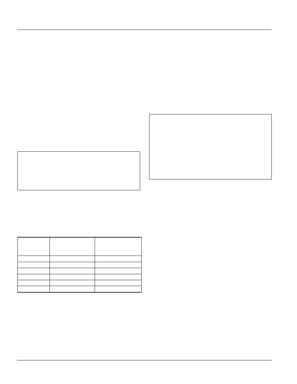
Table 2-7: Instantaneous Thresholds for Power Break I,
Power Break II, WavePro and AKR Trip Units
Breaker
Frame Size
(A)
Instantaneous
Threshold with
Short Time (
× I
N
)
Instantaneous
Threshold without
Short Time (
× I
N
)
800
Off, 2 to 15
Off, 2 to 10
1600
Off, 2 to 15
Off, 2 to 10
2000
Off, 2 to 15
Off, 2 to 10
3200
Off, 2 to 13
Off, 2 to 10
4000
Off, 2 to 9
Off, 2 to 9
5000
Off, 2 to 7
Off, 2 to 7
• RELT instantaneous allows the minimum threshold to go to 1.5X.
GROUND FAULT PROTECTION
The Trip Unit provides two types of ground fault protection:
Ground Fault Summation and Ground Fault CT. These
protections are independent. A related GF alarm function is
available for both types of GF protection, and share the
same pickup level, band choices and tolerances as the GF
trip functions. If both Ground Fault Summation and Ground
Fault CT are desired, order both from the factory because
after delivery these options cannot be changed.
Ground Fault Summation
This protection element operates continuously on the four
current sensor inputs to the trip unit. On four pole breakers,
the fourth pole is built into the circuit breaker. On 3 pole
breakers the 4
th
pole is connected to a neutral sensor
typically mounted in the cable section via the secondary
disconnect. In applications that do not require a neutral
sensor, this 4
th
pole connection must be shorted at the
secondary disconnect to avoid nuisance tripping due to
extraneous noise pickup.
NOTICE
POWERBREAK, AK, AKR, WAVEPRO AND CONVERSION
KITS:
Ground Fault Sum is used for single source and multiple
source Ground Fault schemes.
ENTELLIGUARD G
GF Sum is used for single source ground fault only. For
multiple source ground fault see “Ground Fault CT,”
below.
Ground Fault CT
This protection element is available only on the
EntelliGuard G. It is typically utilized for multi-source
Ground Fault (MSGF) applications in ANSI/UL applications
where sensor data must be shared among multiple trip
units on systems with multiple sources connected in
parallel. Contact your local sales office or the Burlington
factory for details on GE’s recommended MSGF
implementation. When GF CT is specified in a breaker, a
special “interposing CT” is installed in the breaker that is
wired between the breaker’s secondary disconnect and the
trip unit’s CT inputs. The full scale output of this CT is
1.54mA at 100% of external sensor.
The GF pickup value tolerance band is 15% of the set point.
The ground fault pickup settings are listed in Table 2-8 as
multiples of xCT the current sensor rating, in steps of 0.01
xCT. The maximum GF pickup value is limited to 1200 A per
UL standard.
Multiple Ground fault curves are also available: Definite
time, l
2
t slope, l
4
t and a double break special selective
ground fault with dual l
2
t slopes. The pickup in all is drawn
with a 10% tolerance and the bands are drawn with a 15%
current tolerance. In the case of the double break selective
ground fault the first slope is 10% tolerance, the second is
15%. See DES-093A for ground fault curve shapes.