9 - uvr, protective relay, 10 - over current, protective relay, 11 - shunt trip, uvr, over current – GE Industrial Solutions EntelliGuard TU Trip Units User Manual
Page 43: 12 - shunt trip, uvr, protective relay, 13 - shunt trip, over current, protective relay, 14 - uvr, over current, protective relay, Power demand interval, Setting range is 5 to 60 minutes, Waveform capture – load options, Available settings
DEH-4567B
EntelliGuard TU Trip Units: UL/ANSI Models
Setting up the Trip Unit
©2012 General Electric All Rights Reserved
33
• 9 - UVR, Protective Relay
• 10 - Over Current, Protective Relay
• 11 - Shunt Trip, UVR, Over Current
• 12 - Shunt Trip, UVR, Protective Relay
• 13 - Shunt Trip, Over Current, Protective Relay
• 14 - UVR, Over Current, Protective Relay
• 15 - Shunt Trip, UVR, Over Current, Protective Relay
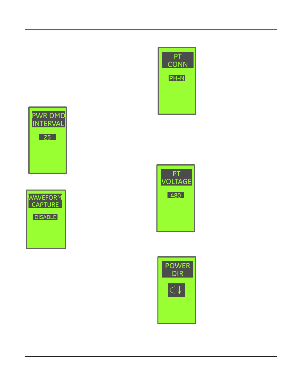
POWER DEMAND INTERVAL
This setting determines the time
interval for power demand
averaging.
Setting range is 5 to 60 minutes.
WAVEFORM CAPTURE – LOAD OPTIONS
Waveform Capture is an optional
feature. If the feature is not installed,
this screen will not be available.
This screen determines the trigger
source for the trip unit’s waveform
capture utility.
Available settings:
• DISABLE – waveform capture will
not be triggered
• MANUAL – the waveform is commanded over Modbus
• OVERCURRENT – GF, LT, ST, INST overcurrent trips will
trigger a capture
• PROT REL – Any protective relay trip will trigger a
capture
• CUR AL 1, CUR AL 2 – Current Alarm 1 or 2 can trigger a
capture
• ALL – any of the above sources will generate a
waveform capture, see “Waveform Capture – Load
Options,” above, on how to view a captures waveform
and clear the waveform
PT CONNECTION
PT connection allows the trip unit
voltage input configuration to be set
to match the wiring of incoming
Potential Transformer (PT).
On a 4 wire wye system, phase to
neutral voltage (PH-N) would be
selected.
On a 3 wire delta system, phase to
phase voltage (PH-PH) would be
selected.
With PH-N selected, power metering
values are shown per-phase as well as totals.
With PH-PH selected, power metering values are shown as
3 phase totals only.
This setpoint must match the wiring of the potential
transformer serving the trip unit.
PT VOLTAGE
PT Voltage configures the trip unit so
that a full scale reading at the
potential transformer input is
correctly scaled.
The transformer ratios and voltage
conditioning circuits used with the
GTU will deliver 1.767VAC at rated
system voltage. This setpoint
determines what voltage is displayed
at full scale, and is normally set to
match the system voltage.
The range of setpoints is 120V to
600V. It can be set in increments of 1V or 10V by scrolling.
POWER DIRECTION
Power Direction describes to the trip
unit how power is flowing through
the breaker, and thus determines the
polarity.
This setting is used to determine the
correct sign for power factor and
other power readings.
It is also critical for the proper
operation of the power reversal
protective relay.
This setting should reflect the
direction of current flow during normal breaker operating
conditions to ensure proper polarity.