Rainbow Electronics DS26504 User Manual
Page 50
DS26504 T1/E1/J1/64KCC BITS Element
50 of 128
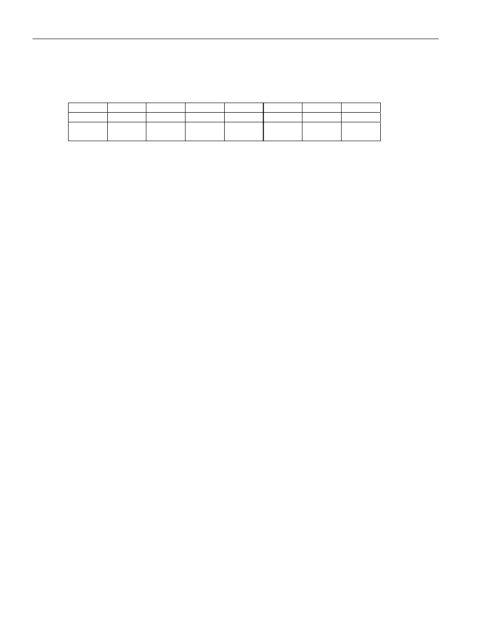
Register Name:
SR2
Register Description:
Status Register 2
Register Address:
16h
Bit
# 7 6 5 4 3 2 1 0
Name RYELC
RAISC
RLOSC
RLOFC
RYEL RAIS RLOS RLOF
Default
0 0 0 0 0 0 0 0
HW
Mode
X X X X X
RAIS
PIN 29
RLOS
PIN 32
LOF
PIN 30
Bit 0: Receive Loss-of-Frame Condition (RLOF). Set when the DS26504 is not synchronized to the received data stream.
Bit 1: Receive Loss-of-Signal Condition (RLOS). Set when 255 (or 2048 if E1RCR.6 = 1) E1 mode or 192 T1 mode
consecutive zeros have been detected. In 6312kHz Synchronization Interface Mode, this bit will be set when the signal
received is out of range as defined by the G.703 Appendix II specification.
Bit 2: Receive Alarm Indication Signal (T1= Blue Alarm, E1= AIS) Condition (RAIS). Set when an unframed all-ones
code is received.
Bit 3: Receive Yellow Alarm Condition (RYEL) (T1 only). Set when a yellow alarm is received.
Bit 4: Receive Loss-of-Frame Clear Event (RLOFC). Set when the framer achieves synchronization; will remain set until
read.
Bit 5: Receive Loss-of-Signal Clear Event (RLOSC). Set when loss-of-signal condition is no longer detected.
Bit 6: Receive Alarm Indication Signal Clear Event (RAISC). Set when the unframed all-ones condition is no longer
detected.
Bit 7: Receive Yellow Alarm Clear Event (RYELC) (T1 only). Set when the yellow alarm condition is no longer detected
.