Fuel piping guidelines – Grain Systems PNEG-707GSI User Manual
Page 240
23. Fuel Piping
240
PNEG-707 12', 18', 24' and 30' GSI Commercial Tower Dryer
Fuel Pipe Lengths*
Fuel Piping Guidelines
Fuel piping can be installed in sections as dryer is erected, or after dryer is complete. Usually top two (2)
sections of fuel piping are installed after fans are installed.
Fuel piping enters dryer through a dryer window. Plan fuel piping so it will terminate as near as possible
to where fuel train will be on foundation.
Seal all threaded pipe connections with heavy duty pipe sealing compound. Fuel piping must be airtight
and satisfy any hazard requirement for the site.
Check all fuel piping is level or plumb.
Check all fuel piping is secured tightly to dryer.
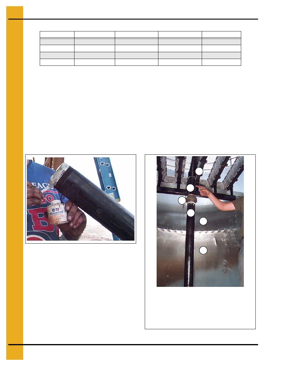
Figure 23I Seal all threaded pipe connections
with heavy duty pipe sealing compound.
Figure 23J Fuel piping installed to burner manifold.
Dryer Model
Pipe Diameter
Outside
Entry
Inside
2500
3"
140"
110"
167"
3000
3"
180"
110"
167"
3500
3"
180"
110"
185"
4000
3"
125" and 94"
110"
185"
*All piping and fittings are schedule 40 black.
A
B
C
D
E
F
A. Burner manifold
B. 3" x 12" Nipple
C. 3" Union
D. 3" Pipe
E. Burner housing
F. Reducer housing