Burner and burner housing (continued) – Grain Systems PNEG-707GSI User Manual
Page 147
14. Burner and Reducer
PNEG-707 12', 18', 24' and 30' GSI Commercial Tower Dryer
147
Burner and Burner Housing (Continued)
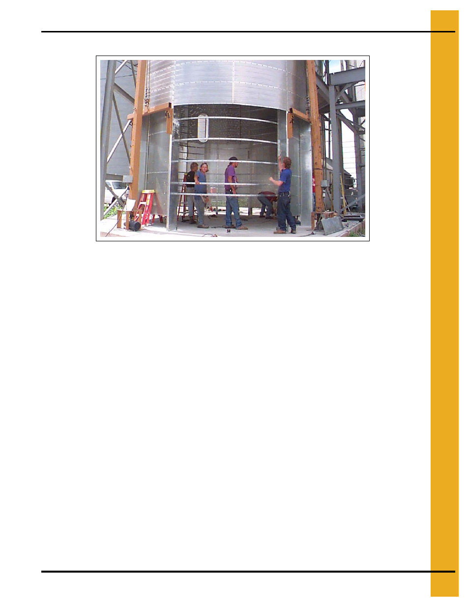
Figure 14G Install rolled plenum channels across gap to maintain shape and stability.
Remove rolled plenum channels when ready to move burner into dryer.
Depending on model,
, burner housing.
See Orientation Section on Page 32
for flat layout for heat section door frame placement.
See Windows and Doors on Page 187
for windows and doors for heat section door and reducer
door installation.
1. Remove rolled plenum channels and bring in both halves of burner housing. See illustration for
up/down orientation.
Also place burner, burner baffle, and other parts inside burner housing to avoid lifting them in later.
(Other parts are burner baffle supports, burner mounting brackets, burner support brackets, and
burner support tees).
2. Align and bolt halves of burner housing. Use 5/16" x 1" galvanized whiz lock bolts and nuts.
3. Overlap and bolt sections of burner housing outlet baffle to top ring of burner housing.
Use 5/16" x 1" galvanized whiz lock bolts and nuts.
4. Check orientation of burner pilot section (with installation points for ignitor and flame sensor).
Plan to install burner so pilot section wiring will make direct run (usually through motor window to
control box.)
5. Measure to determine correct bolt hole knock-outs for burner support parts. Knock out bolt holes
as required.
6. Install burner to burner housing as follows.
a. Loosely bolt four (4) burner mounting brackets to burner housing. Bracket them (orient as mirror
images). Use 3/8" x 1" galvanized bolts, nuts. Install washers on outside of burner housing.
b. Lift and temporarily support burner while installing burner support brackets below burner.
Loosely bolt two (2) burner support brackets to burner mounting brackets. Use 1/2" x 1-1/2"
galvanized bolts and nuts. Position burner over burner support brackets.