5 vrrp configuration examples, 1 one subnet network example, Figure 110 vrrp configuration: summary – ZyXEL Communications GS-4012F/4024 User Manual
Page 206: Table 80 vrrp configuring: vrrp parameters
GS-4012F/4024 User’s Guide
Chapter 31 VRRP
205
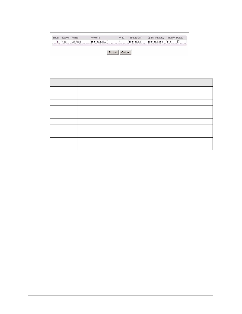
Figure 110 VRRP Configuration: Summary
The following table describes the labels in this screen.
31.5 VRRP Configuration Examples
The following sections show two VRRP configuration examples on the switch.
31.5.1 One Subnet Network Example
The figure below shows a simple VRRP network with only one virtual router VR1 (VRID =1)
and two switches. The network is connected to the WAN via an uplink gateway G
(172.21.1.100). The host computer X is set to use VR1 as the default gateway.
Table 80 VRRP Configuring: VRRP Parameters
LABEL
DESCRIPTION
Index
This field displays the index number of an entry.
Active
This field shows whether a VRRP entry is enabled (Yes) or disabled (No).
Name
This field displays a descriptive name of an entry.
Network
This field displays the IP address and subnet mask of an interface.
VRID
This field displays the ID number of a virtual router.
Primary VIP
This field displays the IP address of the primary virtual router.
Uplink Gateway This field displays the IP address of the uplink gateway.
Priority
This field displays the priority level (1 to 255) of the entry.
Delete
Click Delete to remove the selected entry from the summary table.
Cancel
Click Cancel to clear the Delete check boxes.