Audio sockets, Interfaces and sockets – codec 6000 mxp – TANDBERG 6000MXP User Manual
Page 31
31
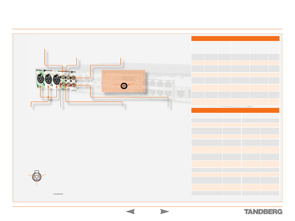
Interfaces and Sockets – Codec 6000
MXP
D 13887.08
MAY 2008
TANDBERG 3000
MXP
&
6000
MXP
REFERENCE GUIDE FOR SYSTEM INTEGRATORS
Audio Sockets
Microphone Inputs
Nos. 1–3
.
Three balanced
microphone inputs for
electret microphones
balanced, 24V phantom
powered via XLR
connectors.
The phantom powering
of XLR socket No. 3 can
be switched off. The
Mic. input No. 3 will
then be a balanced line
level input.
Tip!
Unused, but connected
audio inputs should be set
to Off to avoid unwanted
audio/noise.
Use
Audio Input No. 4
to connect to an external
microphone amplifier or to
an external mixer.
Use
Audio Input No. 5
to
connect to external playback
devices or to telephone add-on
hybrids. For systems configured
with stereo I/O, connect the
VCR/DVD left channel to this
input.
Use
Audio Input No. 6
to
connect a VCR or DVD player
to the system. For systems
configured with stereo I/O,
connect the VCR/DVD right
channel to this input.
Tip!
Audio inputs Nos. 5
& 6 are not equipped with
acoustic echo canceller.
Connecting microphones to
these inputs can therefore
not be recommended.
Use
Audio Output No. 2
(the
AUX output) to provide a mixed
signal consisting of audio from
the local side (AUX input not
included) and audio from the
far end.
This output should be used
when connecting a telephone
add-on system.
For system configured with
stereo I/O and with SPDIF
†
active on Audio Output No. 1,
this output will provide the VCR
left channel stereo information.
For systems configured with
stereo I/O, stereo speakers and
SPDIF
†
not active, this output
will provide the right channel of
the loudspeaker signal (the left
channel will be provided on the
Audio Output No. 1).
Use
Audio Output No. 3
(the VCR output) to provide
a mixed signal consisting
of audio from the local side
(VCR input not included)
and audio from the far end.
This output should be used
when connecting a VCR to
the system.
For system configured with
stereo I/O and with SPDIF
†
active on Audio Output No.
1, this output will provide
the VCR right channel
stereo information.
For systems configured
with stereo I/O, stereo
speakers and SPDIF
†
not
active, this output will
provide the mix of left and
right channel of the VCR
out signal.
XLR pin-out
External view of socket
Pin 1: Gnd
Pin 2: Hot
Pin 3: Cold/neutral
1
2
3
Use
Audio Output No. 1
to
provide a mixed signal of audio
from far end and local external
devices connected to input 5 &
6, in addition to dial tones.
This output should be connected
to the local loudspeaker system,
which may, or may not, include
the TANDBERG Digital Natural
Audio Module.
For systems configured with
stereo speakers and SPDIF
†
active, the left and right channel
of the loudspeaker signal will
both be provided on this output.
For systems configured with
stereo speakers and SPDIF
†
not active, the left channel of
the loudspeaker signal will be
present on this output. The right
loudspeaker channel will be
provided on Audio Output No. 2.
†
SPDIF (Sony/Philips Digital Interface)
is used by the Digital Natural Audio module.
Stereo Settings
Settings
Output Response
Out 1
mode
Stereo
I/O mode
Stereo
speakers
Audio Out 1
Audio Out 2
Audio
Out 3
Analogue
Off
Off
Loudspeaker
mono
Aux
VCR
Analogue
Off
On
Loudspeaker L
Loudspeaker R
VCR
Analogue
On
Off
Loudspeaker
mono
VCR L
VCR R
Analogue
On
On
Loudspeaker L
Loudspeaker R
VCR
SPDIF
Off
Off
Loudspeaker
mono
Aux
VCR
SPDIF
Off
On
Loudspeaker
L & R
Aux
VCR
SPDIF
On
Off
Loudspeaker
mono
VCR L
VCR R
SPDIF
On
On
Loudspeaker
L & R
VCR L
VCR R
Tip!
Audio signal levels
expressed in volts and dBu
can be found overleaf.
NoTe!
Audio
inputs 4–6
are referred
to as Line
input 1–3 in
the API.
Hardware Information
Microphone(s)
Audio Input(s)
Audio Outputs
Signal type
Balanced
Unbalanced
Socket
XLR-F
RCA/phono
Input impedance
2400 W
(pin 2–3)
10 kW
Output impedance
680 W
Max input level when set to
min. input level
83 mVpp
15.5 Vpp
Max output level when set to
max. output level
15.5 Vpp
Max input level when set to
max. input level
6.2 mVpp
1.2 Vpp
Max output level when set to
min. output level
1.2 Vpp
Gain range
22.5 dB (16 steps of 1.5 dB)
Phantom power
24 V ± 5 %
Phantom power resistor
pin 2
1200 W
Phantom power resistor
pin 3
1200 W
Max phantom power current
12 mA
RCA pin-out
External view of socket
GND
Signal