Configulation, 2 display – Omega RD200 User Manual
Page 16
-12-
3. CONFIGULATION
3.2 Display
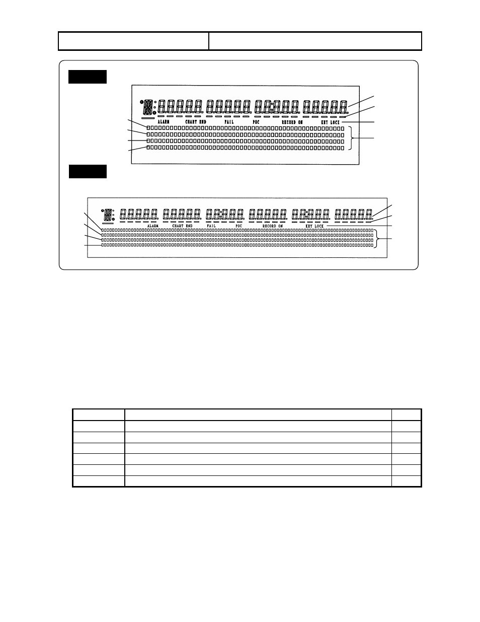
RD200
RD2800
(1) Characters
● Operation mode: Displays measured value, time, chart speed, and alarm status of each channel (CH).
See Section 6.4 for details.
● Programming mode: Displays programming items and programming parameters in an interactive method.
(2) Underline
Shows the trace printing color of each channel (CH).
(CH 1: Red, CH 2: Green, CH3: Blue, CH 4: Brown)
These underlines also function as a cursor appearing at the digit for programming parameter in the programming
mode.
(3) Status
Display Lighting
condition
Section
ALARM
When an alarm activates.
10.3
CHART END When the end of chart is detected.
6.2
FAIL
When the hardware related to servo-circuit/mechanism is abnormal.
POC
When the time axis synchronization is enabled.
9.6
RECORD ON When the printing is on (enable).
6.2
KEY LOCK
When the keys are locked.
11.12
(4) Bargraph
The bargraphs indicate the measured value of each channel in an analog form. These indications are
interlocking to the positions of the pens for trace printing.
Resolution RD200: 1/50 (2%), 51 segments
RD2800: 1/100 (1%), 101 segments
CH 1
CH 2
CH 3
CH 4
CH 1
CH 2
CH 4
CH 3
CH 1
CH 2
CH 3
CH 4
CH 1
CH 2
CH 3
CH 4
CLOCK
CHART SPPED
(1)
(2)
(3)
(4)
(1)
(2)
(3)
(4)