Connecting to a 100-pin 0.65mm pitch foot pattern, Caution – Renesas R0E530640MCU00 User Manual
Page 34
R0E530640MCU00 User’s Manual
2. Setup
REJ10J1733-0100 Rev.1.00 Apr. 01, 2008
Page 34 of 229
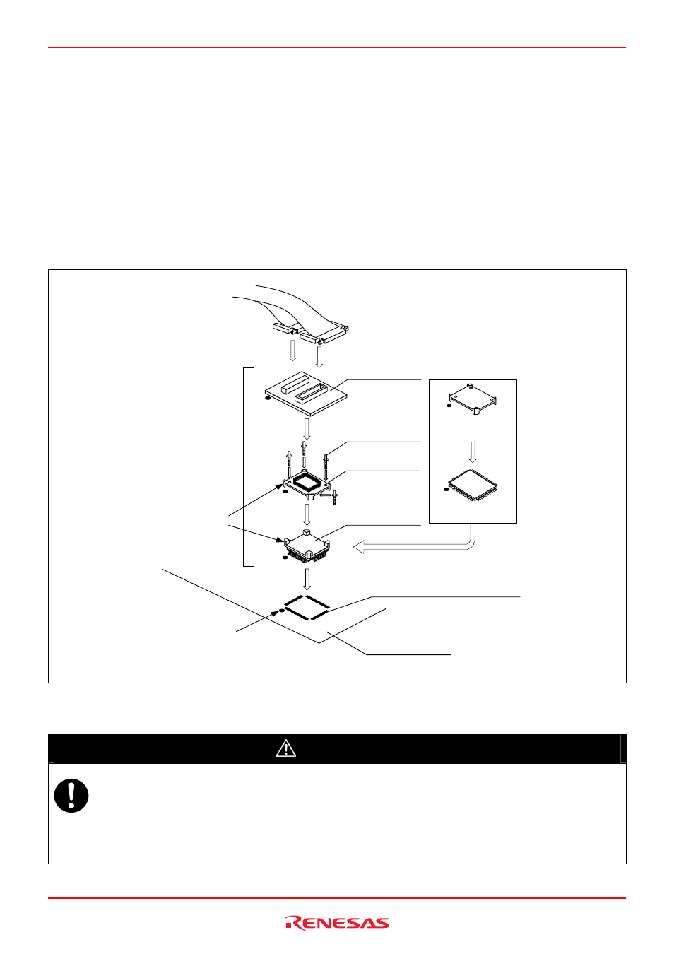
2.9.1 Connecting to a 100-pin 0.65mm Pitch Foot Pattern
The following is a procedure of connecting to a 100-pin 0.65mm pitch foot pattern on the user system using the
R0E0100TNPFJ00 (not included). For details on the R0E0100TNPFJ00 (not included), refer to its user's manual.
(1) Attach the NQPACK100RB included with the R0E0100TNPFJ00 to the user system.
(2) Attach the YQPACK100RB included with the R0E0100TNPFJ00 to the NQPACK100RB and secure it with the YQ-
GUIDEs.
(3) Attach the R0E0100TNPFJ00 to the YQPACK100RB.
(4) Attach the CN2 side of the R0E0100TNPFJ00 to the CN2 side of the flexible cable.
(5) Attach the CN1 side of the R0E0100TNPFJ00 to the CN1 side of the flexible cable.
(5)
(1)
100-pin 0.65mm pitch
(PRQP0100JD-B) foot pattern
No. 1 pin
User system
FLASH version
MCU, etc.
Evaluation with
actual MCU
: These four products are
available in one package.
YQPACK100RB
NQPACK100RB
(2)
(3)
YQ-GUIDE (×4)
These corners
are not round.
*
HQPACK100RB168
(not included)
R0E0100TNPFJ00
(4)
*
Figure 2.11 Connecting to a 100-pin 0.65mm pitch foot pattern
CAUTION
Notes on Connecting the User System:
z Take care not to attach a converter board in a wrong direction. It may cause a fatal damage to the emulator and
user system.
z The connectors of the R0E0100TNPFJ00 are guaranteed for only 50 insertion/removal iterations.
z For purchasing the HQPACK100RB168, contact the following:
Tokyo
Eletech
Corporation
http://www.tetc.co.jp/e_index.htm