Instance #1 use (dspusefirst), Instance #2 state (dspstatesecond), Instance #2 use (dspusesecond) – Patton electronic 3120 User Manual
Page 149: Dsp memory capture, Dsp pcm capture, Dsp debugging events, Dsp connection performance
DSP Connection Performance
149
Model 3120 RAS Administrators’ Reference Guide
11 • Digital Signal Processing (DSP)
Instance #1 Use (dspUsefirst)
Identifies whether the first instance of the DSP is in use or free.
Instance #2 State (dspStateSecond)
Identifies the current state of the second instance of the DSP. See “Instance #1 State (dspStatefirst)” for param-
eter values.
Instance #2 Use (dspUseSecond)
Identifies whether the second instance of the DSP is in use or free.
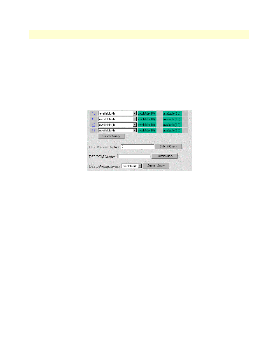
Figure 61. DSP Memory Capture and DSP PCM Capture settings
DSP Memory Capture
This portion of the DSP Settings window (see figure 61) will store the memory content in 5 rotating circular
buffers. Each buffer contains the program and data memory associated with a call on the DSP. The buffer
content is saved when the memory capture is triggered. Do not turn on unless requested by technical support.
DSP PCM Capture
This portion of the DSP Settings window (see figure 61) captures the first 30 seconds of the pulse code modu-
lation on the incoming call on the specified DSP. Do not turn on unless requested by technical support
DSP Debugging Events
Events for each call are automatically saved into a buffer. This buffer holds the last 100 DSP for each DSP.
These are used for analysis by Patton technical staff.
DSP Connection Performance
This window (see figure 62) shows connection summaries and statistics about the individual DSPs. Click on
Connection Summary…
on the DSP main window (see figure 60 on page 147) to display this window.