1 transmit timing, Figure 11. mphy transmit logical timing, 2 receive timing – Intel IXF1104 User Manual
Page 85: Transmit timing, Receive timing, Mphy transmit logical timing, Figure 11 “mphy transmit logical timing, Intel
Intel
®
IXF1104 4-Port Gigabit Ethernet Media Access Controller
85
Datasheet
Document Number: 278757
Revision Number: 009
Revision Date: 27-Oct-2005
5.2.2.1
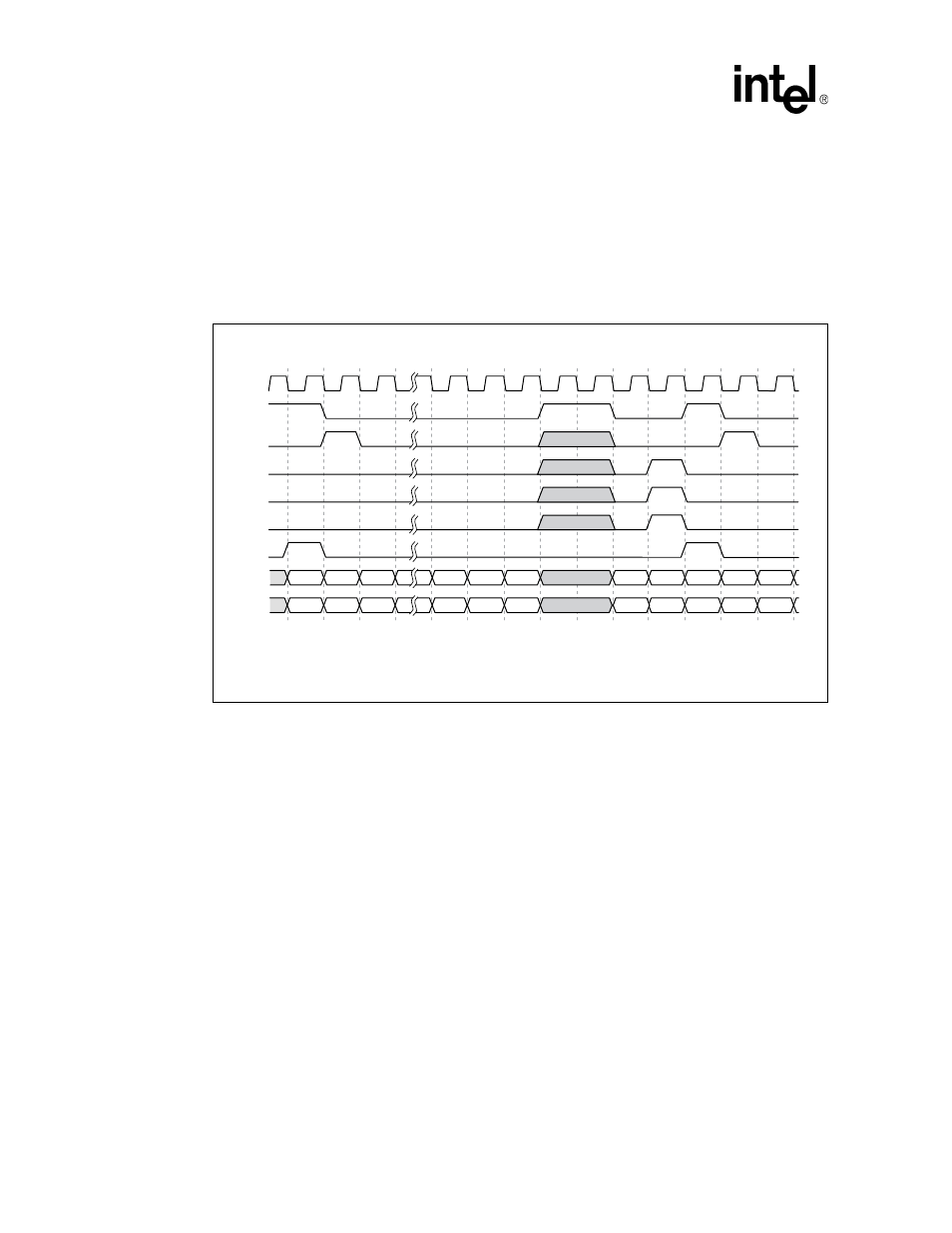
Transmit Timing
In MPHY mode a packet transmission starts with the TSX signal indicating port address
information is on the data bus. The next clock cycle TENB and TSOP indicate present data on the
bus is the first word in the packet and all subsequent clocks will contain valid data as long as TENB
is active or until TEOP is asserted. Data transmission can be temporally halted when TENB goes
high then resumed when TENB is low. The valid bytes in the final word, during an active TEOP,
are indicated by state of TMOD [1:0].
5.2.2.2
Receive Timing
A packet is received when RSX indicates port address information on the data bus followed by
RSOP to indicate the data bus contains the first word of a packet. All subsequent data is valid only
while RVAL is High and until REOP is asserted. Receive data can be temporarily halted when
RENB is de-asserted and starts again on the second rising edge of RFCLK following the assertion
of RENB. RMOD indicates the number of valid bytes in the last transfer when REOP is asserted.
Figure 11. MPHY Transmit Logical Timing
B3216-02
TFCLK
TENB
TSOP
TEOP
TMOD
[1:0]
TERR
TSX
TDAT
[31:0]
TPRTY
0000
B0-B3
B4-B7
B48-B51
B44-B47
B52-B55
B60-B64
B56-B59
0001
B0-B3
B4-B7
1. Applies to all transmit packet available signals (STPA, PTPA, DTPA_0:3).