Figure 28. random read, 8 led interface, 1 modes of operation – Intel IXF1104 User Manual
Page 115: Led interface 5.8.1, Modes of operation, Random read, Intel
Intel
®
IXF1104 4-Port Gigabit Ethernet Media Access Controller
115
Datasheet
Document Number: 278757
Revision Number: 009
Revision Date: 27-Oct-2005
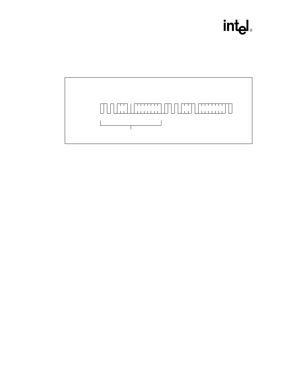
The IXF1104 MAC initiates a current address read by sending a device address with the Read/
Write bit set High. The optical module acknowledges the device address and serially clocks out the
data word. The IXF1104 MAC does not respond with a zero but generates a stop condition (see
5.8
LED Interface
The IXF1104 MAC uses a Serial interface, consisting of three signals, to provide LED data to some
form of external driver. This provides the data for 12 separate direct drive LEDs and allows three
LEDs per MAC port.
There are two modes of operation, each with its own separate LED decode mapping. Modes of
operation and LEDs are detailed in the following sections.
5.8.1
Modes of Operation
There are two modes of operation: Mode 0 and Mode 1. Mode selection is accomplished by using
the LED_SEL_MODE bit. This bit is globally selected and controls the operation of all ports (see
Table 109 “LED Control ($0x509)” on page 190
).
Mode 0: (LED_SEL_MODE = 0 [Default]): This mode selects operations compatible with the
SGS Thompson M5450 LED Display Driver device. This device converts the serial data stream,
output by the IXF1104 MAC, into 30 direct-drive LED outputs. Although the LED interface is
capable of driving all 30 LEDs, only twelve will be driven in the four-port IXF1104 MAC, three
LEDs per port.
Mode 1: (LED_SEL_MODE = 1): This mode is used with standard TTL (74LS599) or HCMOS
(74HC599) octal shift registers with latches, providing the most general and cost-effective
implementation of the serial data stream conversion.
In addition to these physical modes of operation, there are two types of specific LED data decodes
available for fiber and copper modes. This option is a global selection and controls the operation of
all ports (see
Table 109 “LED Control ($0x509)” on page 190
).
Figure 28. Random Read
DEVICE
ADDRESS
DEVICE
ADDRESS
WORD
ADDRESS
I
2
C_Data Line
DUMMY WRITE
(* = DON'T CARE bit for 1k)
ST
A
R
T
S
T
A
R
T
R
E
A
D
S
T
A
R
T
W
R
I
T
E
S
T
O
P
M
S
B
M
S
B
M
S
B
L
S
B
R
/
W
L
S
B
DATAn
L
S
B
A
C
K
N
O
A
C
K
A
C
K
*