Table 36. led behavior (copper mode), 9 cpu interface, Cpu interface – Intel IXF1104 User Manual
Page 120: Led behavior (copper mode), Table 36
Intel
®
IXF1104 4-Port Gigabit Ethernet Media Access Controller
Datasheet
120
Document Number: 278757
Revision Number: 009
Revision Date: 27-Oct-2005
5.8.6.1.2
Copper LED Behavior
5.9
CPU Interface
The CPU interface block provides access to registers and statistics in the IXF1104 MAC. The
interface is asynchronous externally and operates within the 125 MHz clock domain internally. The
interface provides access to the following:
•
Receive statistics registers
•
Transmit statistics registers
•
Receive FIFO registers
•
Transmit FIFO registers
•
Global configuration and control registers
•
MAC_0 to MAC_3 registers
The CPU interface width can be configured with the two strap signals (UPX_WIDTH[1:0]) to
operate as an 8-bit, 16-bit, or 32-bit bus. All internal accesses to registers are 32-bit (4, 2, or 1 data
cycles respectively are required to fully access a register). When operating in 8-bit or 16-bit mode,
read data for bytes [3:1] is strobed into read holding registers when byte [0] is read. Subsequent
reads of bytes {1, 2, 3} in byte mode or of bytes {2,3} in 16-bit mode are supplied from the holding
register independent of the upper address bits. On write accesses in 8-bit mode, the data of bytes
{0, 1, 2} is similarly captured in internal write holding registers and the complete 32-bit write is
committed when byte[3] is written to the IXF1104 MAC. When writing in 16-bit mode, bytes [1:0]
are captured, and the double-word is committed when bytes [3:2] are written. The complete
address for write is ignored (except for the write which causes the commit operation).
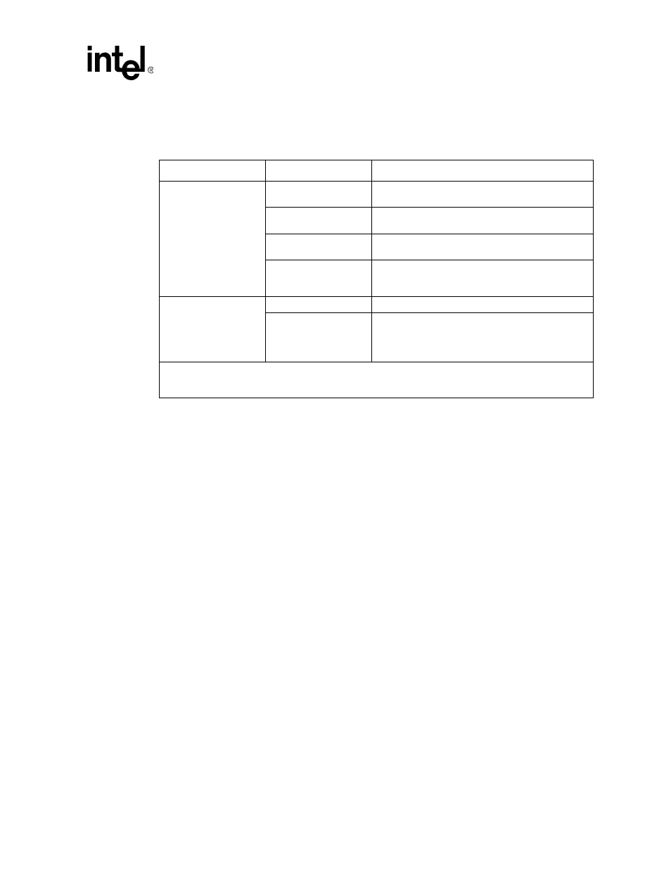
Table 36. LED Behavior (Copper Mode)
Type
Status
Description
Link LED
Off
Port does not have a remote fault and
bit is not set.
Amber On
Port has an RGMII RXERR condition detected and
“LED Control ($0x509)” on page 190
bit is set
Amber Blinking
is not set.
Green On
“LED Control ($0x509)” on page 190
bit is set and port
does not have an RGMII RXERR error or remote fault
condition present.
Activity LED - Green
Off
Port is not transmitting and receiving data.
Blinking
“LED Control ($0x509)” on page 190
set: Port is
transmitting and/or receiving.
“LED Control ($0x509)” on page 190
not set: Port is
receiving data.
NOTE:
assumes the port is enabled in the
and the LEDs are enabled in the
“LED Control ($0x509)” on page 190
. If a port is not
enabled, all the LEDs for that port are off. If the LEDs are not enabled, all of the LEDs are off.