Table 46. spi3 receive interface signal parameters, Spi3 receive interface signal parameters, Table 46 “spi3 receive interface signal parameters – Intel IXF1104 User Manual
Page 138: Table 46
Intel
®
IXF1104 4-Port Gigabit Ethernet Media Access Controller
Datasheet
138
Document Number: 278757
Revision Number: 009
Revision Date: 27-Oct-2005
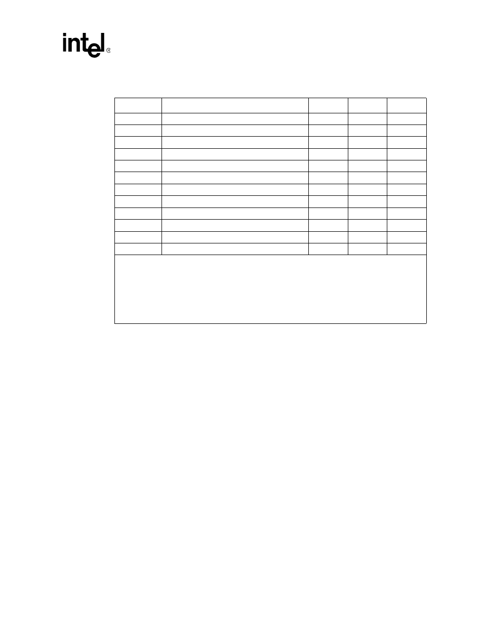
Table 46. SPI3 Receive Interface Signal Parameters
Symbol
Parameter
Min Max
Units
–
RFCLK frequency
90
133
MHz
–
RFCLK duty cycle
45
55
%
Tsrenb
RENB setup time to RFCLK
1.8
–
ns
Threnb
RENB hold time to RFCLK
0.5
–
ns
TPrdat
RFCLK High to RDAT valid
1.5
3.7
ns
TPrprty
RFCLK High to RPRTY valid
1.5
3.7
ns
TPrsop
RFCLK High to RSOP valid
1.5
3.7
ns
TPreop
RFCLK High to REOP valid
1.5
3.7
ns
TPrmod
RFCLK High to RMOD valid
1.5
3.7
ns
TPrerr
RFCLK High to RERR valid
1.5
3.7
ns
TPrval
RFCLK High to RVAL valid
1.5
3.7
ns
TPrsx
RFCLK High to RSX valid
1.5
3.7
ns
NOTES: Receive I/O Timing
1. When a setup time is specified between an input and a clock, the setup time is the time in nanoseconds
from the 1.4-volt point of the input to the 1.4-volt point of the clock.
2. When a hold time is specified between an input and a clock, the hold time is the time in nanoseconds from
the 1.4-volt point of the clock to the 1.4-volt point of the input.
3. Output propagation time is the time in nanoseconds from the 1.4-volt point of the reference signal to the
1.4-volt point of the output.
4. Maximum propagation delays are measured with a 30 pF load when operating OIF-SPI3 standard 104
MHz. Over-clocked rates of 125 MHz or higher are measured using a load of 20 pF.