3 rgmii ac timing specification, Figure 37. rgmii interface timing, Table 48. rgmii interface timing parameters – Intel IXF1104 User Manual
Page 141: Rgmii ac timing specification, Rgmii interface timing, Rgmii interface timing parameters
Intel
®
IXF1104 4-Port Gigabit Ethernet Media Access Controller
141
Datasheet
Document Number: 278757
Revision Number: 009
Revision Date: 27-Oct-2005
7.3
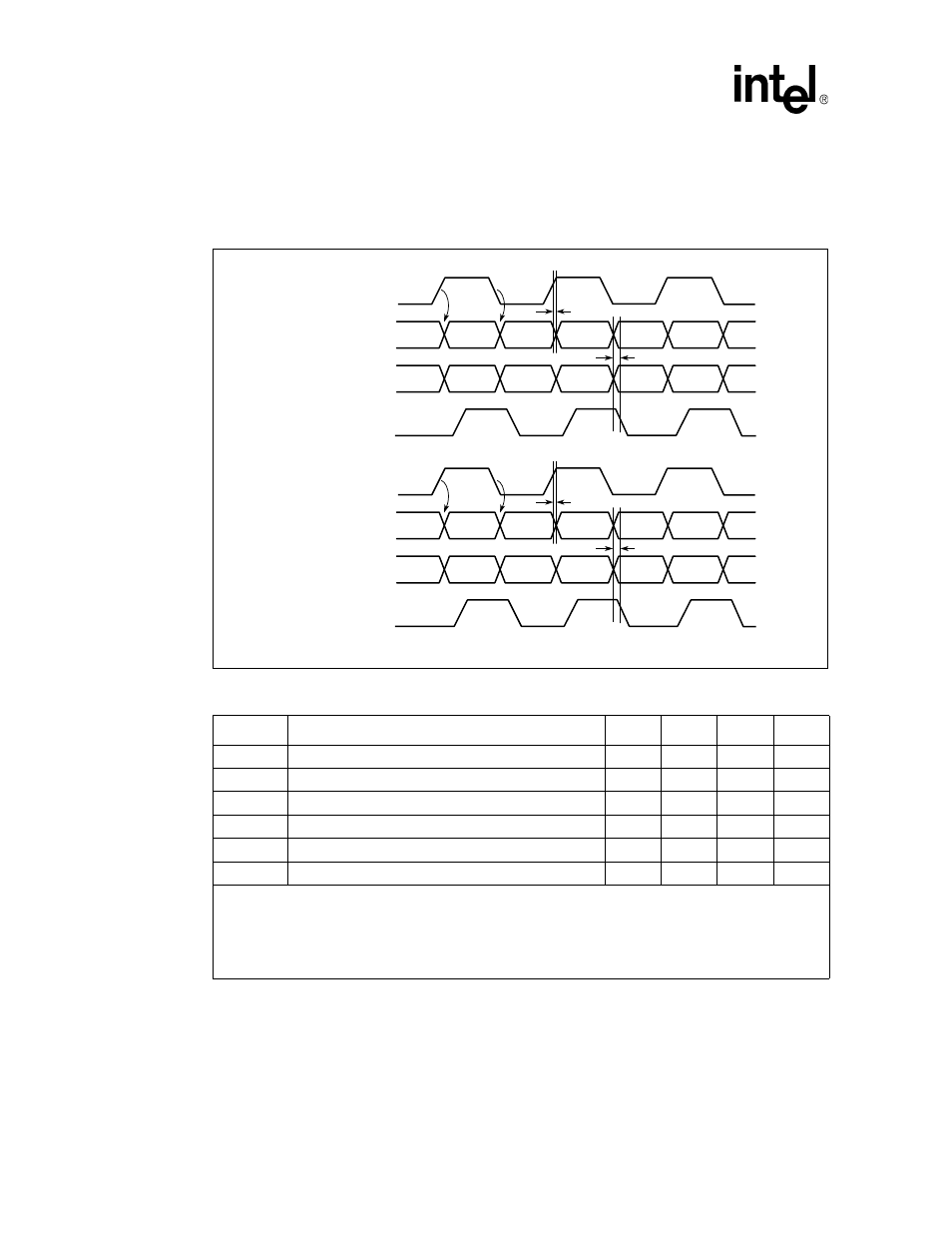
RGMII AC Timing Specification
provide RGMII interface timing parameters.
Figure 37. RGMII Interface Timing
Table 48. RGMII Interface Timing Parameters
Symbol
Parameter
Min
Typ
Max
Unit
TskewT
Data-to-Clock Output Skew (at Transmitter)
-500
0
500
ps
TskewR
Data-to-Clock Input Skew (at Receiver)
1
1
–
2.8
ns
Tcyc
Clock Cycle Duration
2
7.2
8
8.8
ns
Duty_T
Duty Cycle for Gigabit
2
45
50
55
%
Duty_G
Duty Cycle for 10/100T
3
40
50
60
%
Tr/Tf
Rise/Fall Time (20–80%)
–
–
.75
ns
1. This implies that PC board design requires clocks to be routed so that an additional trace delay of greater
than 1.5 ns is added to the associated clock signal.
2. For 10 Mbps and 100 Mbps Tcyc scales to 400 ns +/– 40 ns and 40 ns +/– 4 ns respectively.
3. Duty cycle may be stretched/shrunk during speed changes or while transitioning to a received packet’s
clock domain, as long as minimum duty cycle is not violated and stretching occurs for no more than three
Tcyc of the lowest speed transitioned between.
B3251-01
TSkewT
TXC
(at Transmitter)
TXC
(at Receiver)
TD[3:0]
TX_CTL[n]
TSkewR
TD[3:0]
TD[7:4]
TXEN
TXERR
TSkewT
RXC
(at Transmitter)
RXC
(at Receiver)
RD[3:0]
RX_CTL
TSkewR
RD[3:0]
RD[7:4]
RXDV
RXERR