5 port protocol operation, 6 clock and data transitions, Figure 25. data validity timing – Intel IXF1104 User Manual
Page 113: Figure 26. start and stop definition timing, Port protocol operation, Clock and data transitions, Data validity timing, Start and stop definition timing
Intel
®
IXF1104 4-Port Gigabit Ethernet Media Access Controller
113
Datasheet
Document Number: 278757
Revision Number: 009
Revision Date: 27-Oct-2005
5.7.3.5
Port Protocol Operation
5.7.3.6
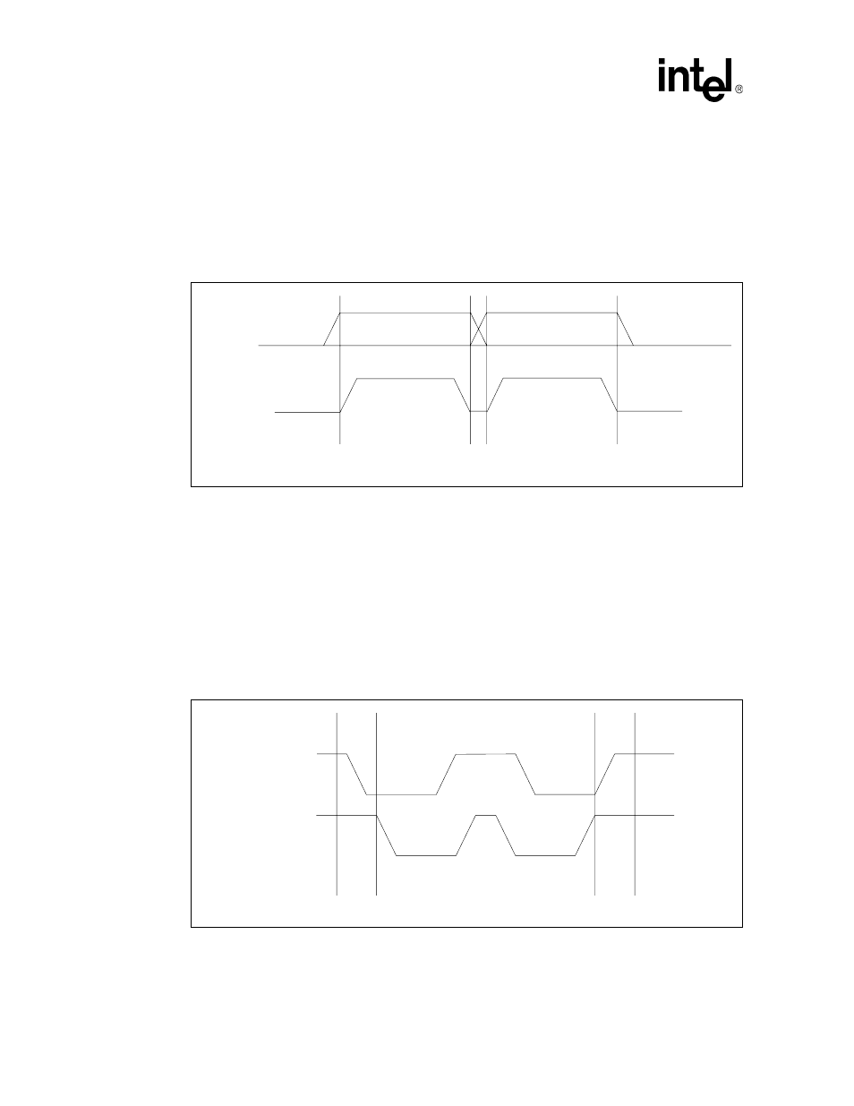
Clock and Data Transitions
The I
2
C_DATA is normally pulled High with an extra device. Data on the I
2
C_DATA pin changes
only during the I
2
C_CLK Low time periods (see
). Data changes during I
2
C_CLK High
periods indicate a start or stop condition.
5.7.3.6.1
Start Condition
A High-to-Low transition of I
2
C_DATA, with I
2
C_CLK High, is a start condition that must
precede any other command (see
5.7.3.6.2
Stop Condition
A Low-to-High transition of the I
2
C_DATA with I
2
C_CLK High is a stop condition. After a Read
sequence, the stop command places the E²PROM and the optical module in a standby power mode
(see
Figure 25. Data Validity Timing
DATA STABLE
DATA STABLE
DATA
CHANGE
I
2
C_Data
I
2
C_Clk
Figure 26. Start and Stop Definition Timing
START
STOP
I
2
C_Data
I
2
C_Data