2 program status (ps), Program status (ps) – FUJITSU FR family 32-bit microcontroller instruction manuel CM71-00101-5E User Manual
Page 43
19
CHAPTER 3 REGISTER DESCRIPTIONS
3.3.2
Program Status (PS)
The program status (PS) indicates the status of program execution, and consists of the
following three parts:
• Interrupt level mask register (ILM)
• System condition code register (SCR)
• Condition code register (CCR)
■
Overview of Program Status Register
The program status register consists of sections that set the interrupt enable level, control the program trace
break function in the CPU, and indicate the status of instruction execution.
■
Program Status Register Configuration
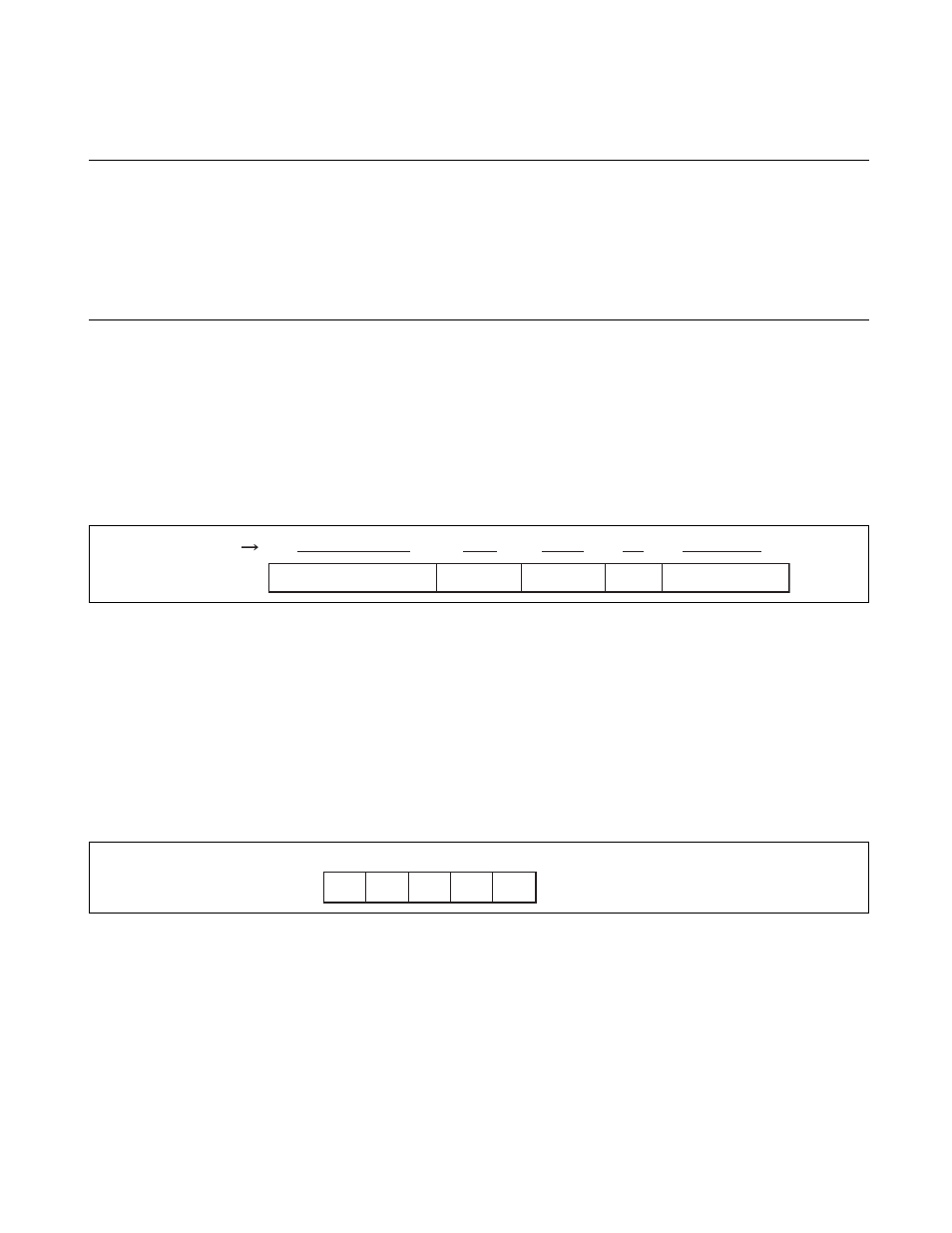
Figure 3.3-2 shows the configuration of the program status register.
Figure 3.3-2 Program Status Register Configuration
■
Unused Bits in the Program Status Register
Unused bits are all reserved for future system expansion. Write values should always be "0". The read
value of these bits is always "0".
■
Interrupt Level Mask Register (ILM: Bit 20 to bit 16)
●
Bit Configuration of the ILM Register
Figure 3.3-3 Bit Configuration of the ILM Register
●
ILM Functions
The "ILM" determines the level of interrupt that will be accepted. Whenever the "I" flag in the "CCR"
register is "1", the contents of this register are compared to the level of the current interrupt request. If the
value of this register is greater than the level of the request, interrupt processing is activated. Interrupt
levels are higher in priority at value approaching "0", and lower in priority at increasing values up to "31".
Note that bit "ILM4" differs from the other bits in the register, in that setting values for this bit are
restricted.
Figure 3.3-4 shows the functions of the "ILM".
PS
Unused
Unused
ILM
SCR
CCR
Bit no.
31
2120
1615
1110
0807
00
20
19
18
17
16
ILM
ILM4 ILM3 ILM2 ILM1 ILM0 Initial value: 01111
B