Section iii maintenance – Gradall 544D (9136-4003) Service Manual User Manual
Page 64
REPLACING, ADDING OR REMOVING WORK
SECTION ASSEMBLIES
NOTE
Before disassembly, it is suggested that each work
section be marked numerically to avoid incorrect
reassembly.
SECTION III
MAINTENANCE
Remove four hex nuts (Item 29, Figure 4-1 ) from the
right end of the valve assembly using a 9/16" socket
wrench. If the valve assembly consists of only one or
two work sections, bolts and lock washers must be
removed instead.
Remove the outlet cover and each section by sliding
from assembly studs (Item 29, Figure 4-1).
If work sections are to be added or subtracted from
the valve assembly, the four studs must be removed
from the inlet cover and replaced with studs of proper
length. Refer to Table 3-1.
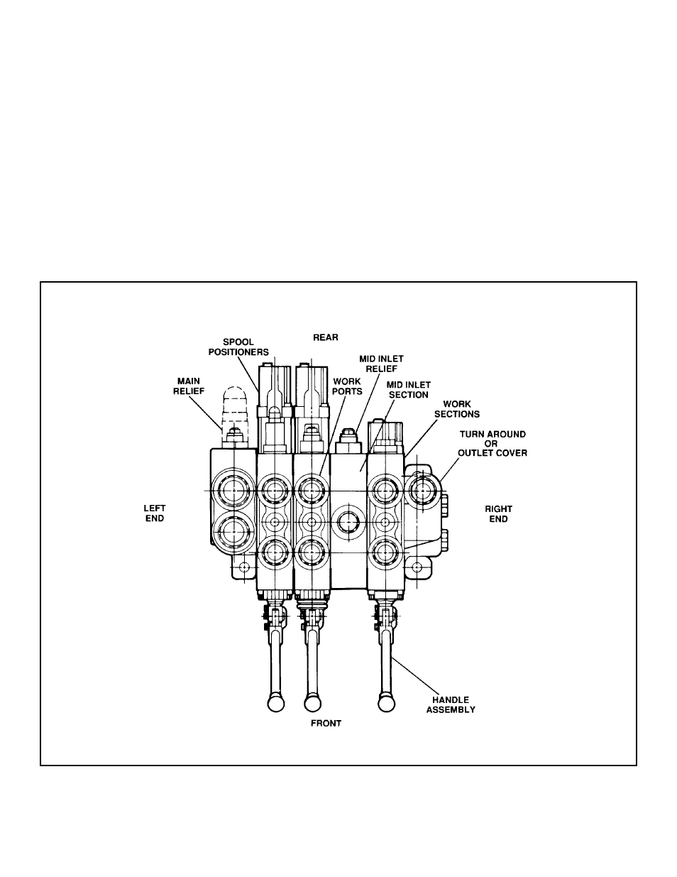
Figure 3-1. Schematic View of a Typical Model V40 Control Valve Assembly.
For clarification, the side containing the
inlet cover (the cover containing the main
relief valve) will be called the left end of the
valve assembly. Refer to Figure 3-1.
1.
2.
3.
4.
3-0