Removing the complete boom assembly – Gradall 544D (9136-4003) Service Manual User Manual
Page 332
9.5
E
XTEND
C
HAIN
R
OLLER
Removal of the roller is just a matter of slacking off the chain adjustment hardware on the
top of the boom, removing the chain from the clevis, removing and reinstalling the roller.
Adjust the extend chains per instructions in Section 4.
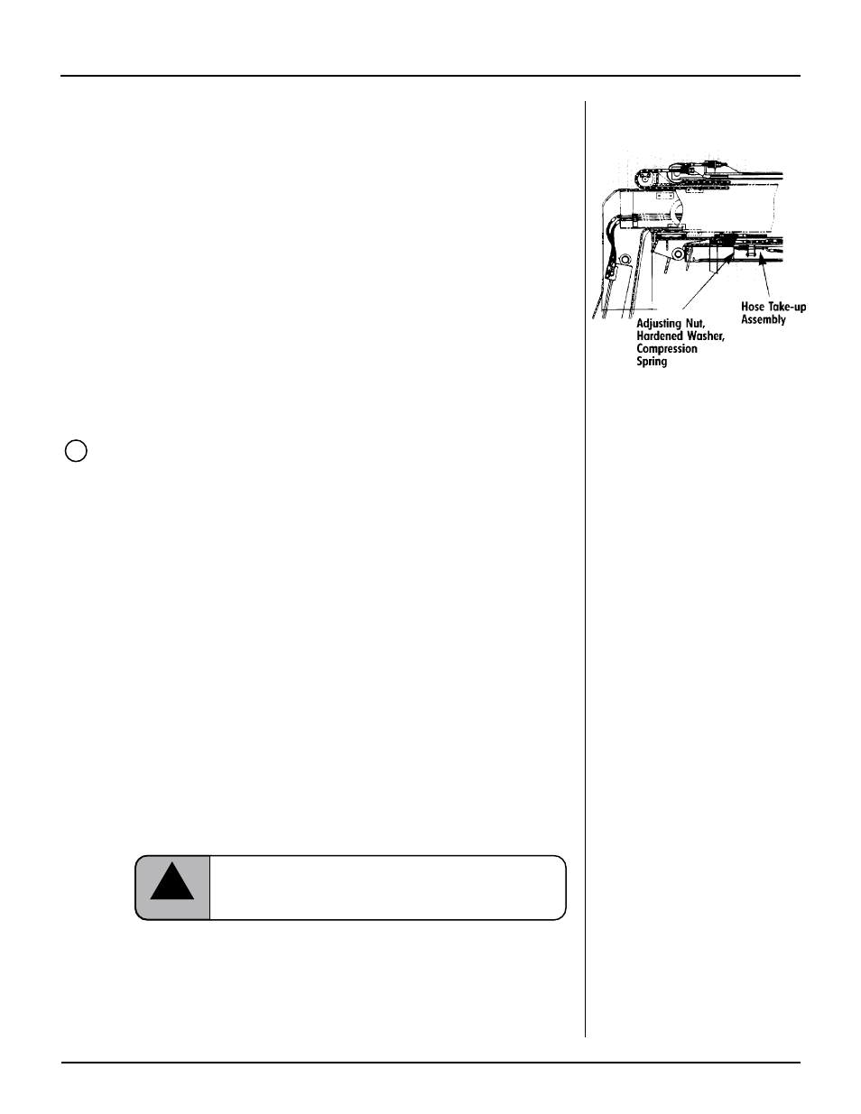
H
OSE
T
AKE-UP
A
SSEMBLY
The Hose Take-Up assembly keeps tension on the hoses inside boom-section 1 that feed
the Hydraulic Sub-Assembly. This prevents the hoses moving uncontrolled whenever the
boom is extended and/or retracted.
The adjusting nut is tightened against the compression spring sufficient to hold tension.
When properly adjusted, there should be 1" from the back of the jam nut to the end of
the hose take-up assembly threads. Torque the jam nut to 100 ft-lb. using LOCTITE 242
on the threads.
R
EMOVING
T
HE
C
OMPLETE
B
OOM
A
SSEMBLY
Preparation
Position the handler in a safe, level, open area well away from personnel and
equipment. Apply the park brake, shift the forward/reverse lever to Neutral and
turn the wheels straight forward.
Turn off the ignition, remove the keys and chock all wheels.
Procure lifting tackle and crane of sufficient size to lift the boom assembly
safely. Note! The assembly weighs approximately 8220 lb.
Install a log line to the front of the boom to help guide it once it clears
the machine.
Fasten slings to boom-section 1 between the crowd cylinder and the boom at the
balance point.
Take the weight off the boom assembly.
Removal
Identify and tag all hydraulic hoses (and any electrical cables).
Separate, plug and cap all hoses. Separate any electrical cables. With the cylinder
hoses blocked off, the boom sections will be locked in position, preventing run-out.
Carefully remove pins from the compensation and lift cylinders.
Confirm that the crane still has the weight of the boom.
Carefully remove the boom base pin.
Lift the boom assembly free of the machine and place it in a designated
work area.
9D
Make sure cylinders do not full uncontrolled to their free position.
This could injure personnel and/or damage components.
!
CAUTION
Note!
Whenever one or more boom
sections must be separated, the best
approach is to remove the complete
assembly from the machine before
attempting separation. The assembly
can then be placed on stanchions
(horses) at a normal working height
(Removing assemblies while the
boom is still installed on the
machine would necessitate working
off ladders or platforms)
F
ORM
N
O.
29702
lllll
544C/544D B
OOM
M
AINTENANCE