Gradall – Gradall 544D (9136-4003) Service Manual User Manual
Page 323
7.2
R
EINSTALLING THE
H
YDRAULIC
S
UB-
A
SSEMBLY
Preparation
Clean and lubricate the inside of the boom sections where the hydraulic
sub-assembly rides.
Install the guide bracket.
Collapse the hydraulic sub-assembly fully.
Fasten both hydraulic carriers together (using tie-wraps or nylon straps).
Retract the booms fully, horizontal.
Reinstallation
Lift the hydraulic sub-assembly in a balanced mode and carefully begin insertion
into boom-section 4.
As the first lie-wrapped area nears the boom, remove the tie-wrap ond continue
insertion (and tie-wrap removal) until the sub-assembly is fully inserted.
Re-connect hydraulic hoses and any optional circuits.
Re-fasten bracket removed under Preparation, Step 5, Page 7.1.
Use long-threaded rod and nuts (3/8 x 16) to aid in pulling the bracket into place
if it protrudes too far from the back of the boom.
C
OMPLETE
B
OOM
A
SSEMBLY:
R
EAR
V
IEW
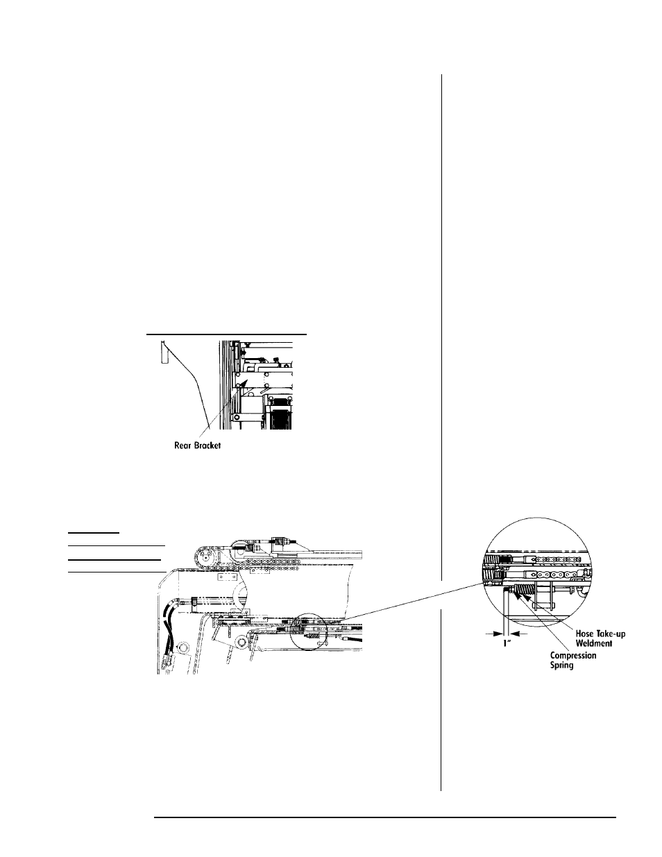
Reinstall the hose take-up compression spring. Torque the jam nut to 100 ft-lb.
There should be 1" from the back of the jam nut to the end of the threads on the
hose take-up weldment.
See Figure Detail in margin
B
OOM
H
EAD:
S
HOWING
H
OSE
T
AKE-UP
W
ILDMENT AT
B
OTTOM,
F
RONT,
B
OOM-
S
ECTION
1
Torque all fasteners and hydraulic fillings per Appendix A, Fastener Torque Chart
and Appendix B, Hose Fitting Torque Chart.
Note!
Be certain the hydraulic
sub-assembly locks in place on
the pin bracket at the bottom of
boom-section 4.
1.
2.
3.
4.
5.
1.
2.
3.
4.
5.
6.
GRADALL
GRADALL