Gradall 544D (9136-4003) Service Manual User Manual
Page 380
is released. In drum brake systems,
this low pressure aids in preventing
air from entering the brakes when
the vehicle is at rest. The residual
valve is removed from models
designed for disc brake systems
because of the drag which would
develop in this type of brake, even
at these relatively low pressures.
When force is applied to the
brake pedal, this force acts through
the PRESSURE REGULATING
SPRING to shift the PRESSURE
REGULATING SPOOL restricting
the flow of oil at LAND “C” to build
up pressure when there is no
requirement for pressure to the
power steering or other hydraulic
device (Figure 3). As the pressure
builds up, a small amount of oil flows
through the ORIFICE and down
through the passage inside the
spool to the REACTION CHAMBER
(Figure 3). At the same time, oil
flows along a groove in the outside
diameter of the MANUAL BRAKE
ACTUATING SLEEVE into the
chamber ahead of the MANUAL
BRAKE ACTUATING SLEEVE
(Figure 2). Flow to the area ahead
of the MANUAL BRAKE
ACTUATING SLEEVE moves the
MASTER CYLINDER PISTON,
building up pressure in the MASTER
CYLINDER which, in turn, builds
pressure in the brake lines. Pressure
in the REACTION CHAMBER
moves the SPOOL back a small
amount against the PRESSURE
REGULATING SPRING, and when
the hydraulic pressure balances
against the PRESSURE
REGULATING SPRING the
pressure is controlled to the
MASTER CYLINDER. The
ORIFICE controls the rate of flow to
the REACTION CHAMBER; hence,
the rate of pressure increases and
stability of the pressure regulating
spool is controlled. Therefore,
system efficiency is maintained
since the power brake valve does
not momentarily take all of the fluid
from the pump. When the pedal effort
is released, the spring in the
REACTION CHAMBER returns the
pressure regulating spool to neutral.
This closes LAND “B” to pressure
and opens LAND “A” which allows
the oil ahead of the spool in the
REACTION CHAMBER to flow to the
return port as well as the oil ahead
of the MANUAL BRAKE
ACTUATING SLEEVE. The spring
in the MASTER CYLINDER returns
the MASTER CYLINDER PISTON.
In case the downstream power
hydraulic system requires a pressure
that is equal to or greater than
(4)
RETURN LINE
PRESSURE
BRAKE LINE
PRESSURE
CONTROLLED
PRESSURE
RETURN LINE
PRESSURE
BRAKE LINE
PRESSURE
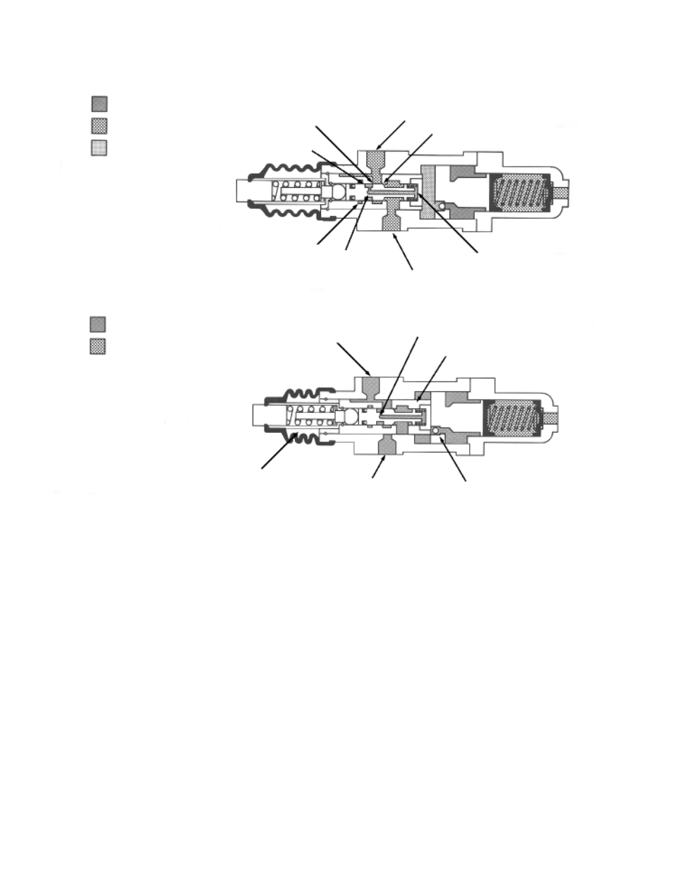
Hydraulic System Pressure Equal to Brake Line Pressure
Schematic of Brake Valve in Manual Operation
FIGURE 4
FIGURE 5
Land “A”
Land “B”
Inlet Port From Pump
Land “C”
Reaction Chamber
Flow Thru Port
Orifice
Return Line Pressure
To Brake Pedal
Manual Brake Actuating Sleeve
To Brake Pedal
Pressure Regulating Sleeve
Flow Thru Port
Orifice
Inlet Port From Pump
Check Valve