Removing the pinchćarm assemblies – HP 750 User Manual
Page 109
1 Remove the drive roller assembly ' page 6Ć49.
2 Push the pinchĆarm lever (located on the right side of the entry platen) into the down
position.
3 On the right side of the plotter, disconnect the rockerĆplate tension spring to relieve any
remaining tension on the pinchĆarm lift mechanism.
4 On the right side of the plotter, loosen the camĆjournal screw by turning it 12 times
counterĆclockwise and push the screw in towards the center of the plotter.
5 Repeatstep 4 and try to pull the cam journal and rear wire link to the right and clear of the
bar cam.
If unsuccessful, turn the camĆjournal screw two more times counterĆclockwise, push the screw
in towards the center of the plotter and try again to pull the cam journal and rear wire link to
the right and clear of the bar cam. Repeat these actions until successful.
Reassembling: Do not overtighten the camĆjournal screw. Doing so
could break the journal, cause the bar cam to enter the sideplate hole
and thus restrict the action of the pinchĆarm lever.
C A U T I O N
Reassembling: Before reinstalling the cam journal, tighten the nut and screw just to the
point where the nut is inside the journal. Reinstall the journal and slightly tighten the screw.
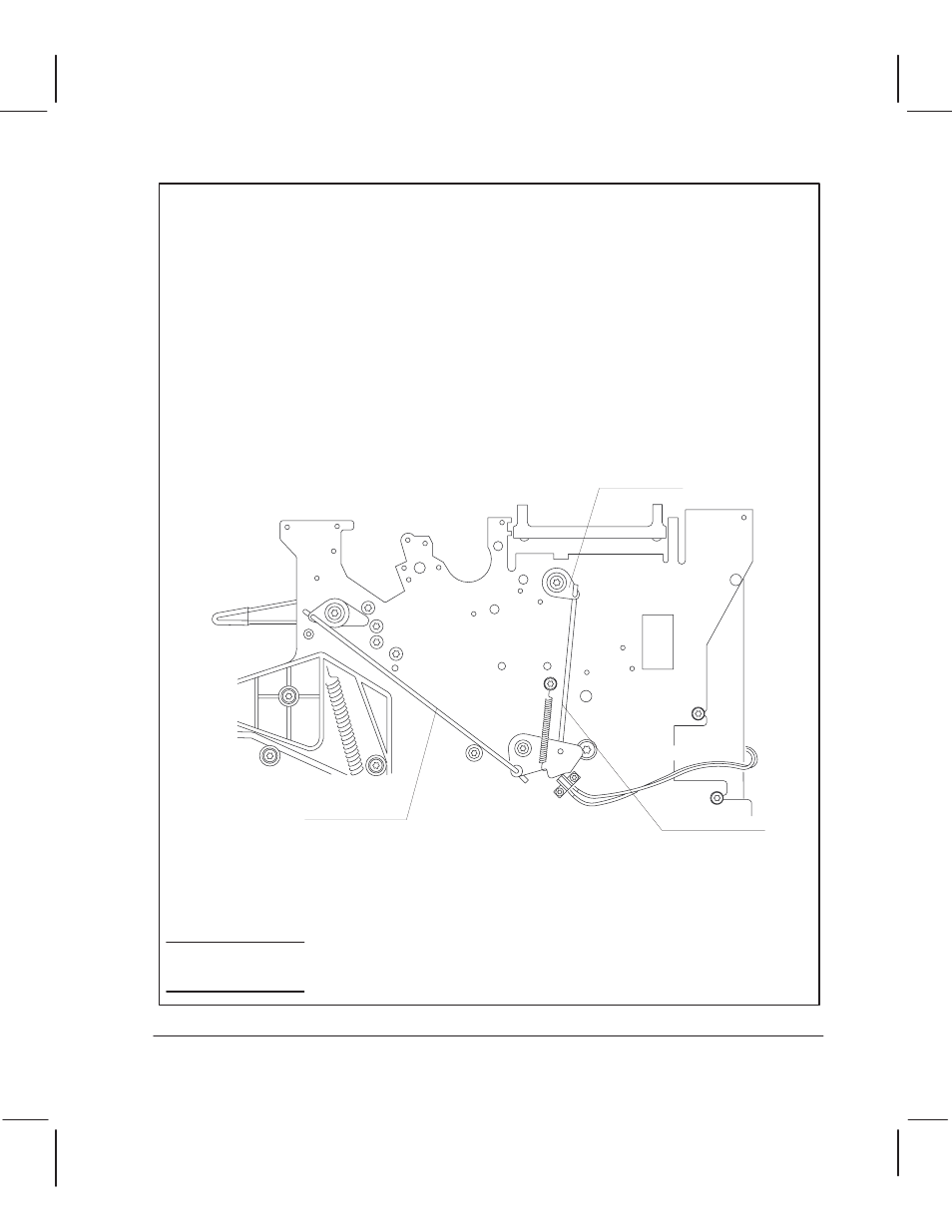
Rear wire link
Front wire link
Cam journal
6-57
Removal and Replacement
C4705-90000
Removing the PinchĆArm Assemblies