HP 30 HP30 User Manual
Page 169
Chapter 7 - Options
7-7
7.2.2
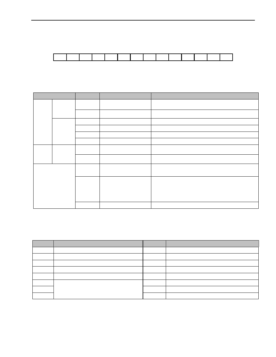
Terminal Configuration (total 14 pins)
AOC BOC A+
A-
B+
B- FBA FBB GND GND +5V +5V VCC VCC
7.2.3 Terminal
Description
Section
Terminal
Name
Description
AOC
A Pulse Input Terminal
Connects A signal of Open Collector type encoder
Open
Collector
Type
BOC
B Pulse Input Terminal
Connects B signal of Open Collector type encoder
A+
A+ Pulse Input Terminal
Connects A+ signal of Line Drive type encoder
A-
A- Pulse Input Terminal
Connects A- signal of Line Drive type encoder
B+
B+ Pulse Input Terminal
Connects B+ signal of Line Drive type encoder
Encoder
Signal
Input
Line Drive
Type
B-
B- Pulse Input Terminal
Connects B- signal of Line Drive type encoder
FBA
Encoder A Pulse Output
Outputs A signal received from the encoder
Signal
Output
Encoder
Signal
Output
FBB
Encoder B Pulse Output
Outputs B signal received from the encoder
+5V
+5V DC Input Terminal
(For Line Drive type)
Provides +5V DC power output to encoder
(5V DC, Minimum 0.5A)
VCC
+12 to 15V DC Input/output
Terminal from External Power
Supply to Encoder
(For Open collector type)
This is the encoder supply voltage. Supply proper voltage
according to the encoder specification.
(+12 to 15V DC, Minimum 0.5A)
Power Supply Input
GND
Ground Terminal
Ground for Power supply and encoder signal
7.2.4
Parameters of Sub-B Board
Code
Parameter Description
Code
Parameter Description
EXT-01 Sub Board Type Display
EXT-21 Pulse Input Signal Adjustment
EXT-14 Usage for Pulse Input Signal
EXT-22 P-Gain
EXT-15 Pulse Input Signal Selection
EXT-23 I-Gain
EXT-16 Encoder Pulse Number
EXT-24 Slip Frequency
EXT-17 Filtering Time Constant
EXT-25 P-Gain for (Sensored) Vector_SPD
EXT-18
EXT-26 I-Gain for (Sensored) Vector_SPD
EXT-19
EXT-27 Forward Torque Limit
EXT-20
Pulse Input Signal Adjustment
EXT-28 Reverse Torque Limit