1 external to ac voltage supply, 2 digital input/output, 1 s0 input – KACO Powador XP100-HV User Manual
Page 82
Page 82
Operating Instructions Powador XP100-HV
U s e r i n t e r f a c e
9.1
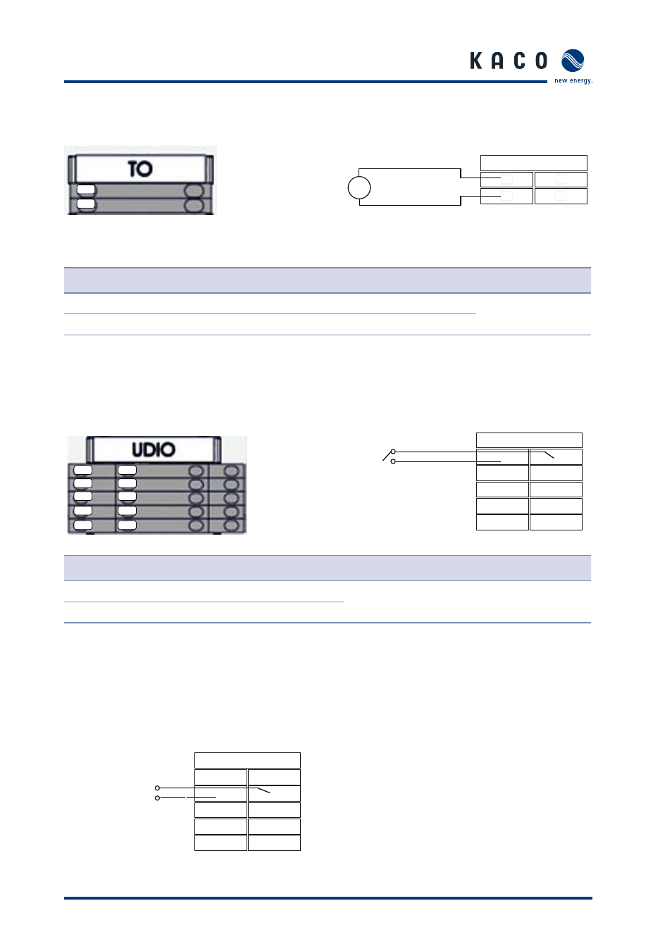
External TO AC voltage supply
Figure 71: TO AC connection
Figure 72: Circuit diagram for TO AC connection
Terminal number
Terminal designation
Specifi cation
Wire cross- section
1a
TO L
230 V L
AWG 14
(2.08 mm
2
)
2a
TO N
230 V N
Table 19: Connections for TO AC auxiliary supply
9.2 Digital
input/output
Figure 73: UDIO connection
Figure 74: UDI1 connection 1, 2
Terminal number
Terminal designation
Specifi cation
Wire cross- section
1a
UDI1 N
Max 27 Vdc, 27 mA
AWG 20
(0.518 mm
2
)
1b
UDI1 P
Table 20: Connections for digital input
9.2.1 S0
input
Figure 75: Connection for S0 input
1a
2a
1a
2a
3a
4a
5a
1b
2b
3b
4b
5b
1a
2a
~
230 V N
230 V L
TO
AC
1b
2b
1b
1b
1a
UDIO
2a
2a
2b
2b
3a
3a
3b
3b
4a
4a
4b
4b
5a
5a
5b
5b
1b
1b
1a
UDIO
2a
2a
2b
2b
3a
3a
3b
3b
4a
4a
4b
4b
5a
5a
5b
5b
Input signal
-
+