Yaskawa Varispeed 626M5 User Manual
Page 98
5.1 Function of the Digital Operator
5 -3
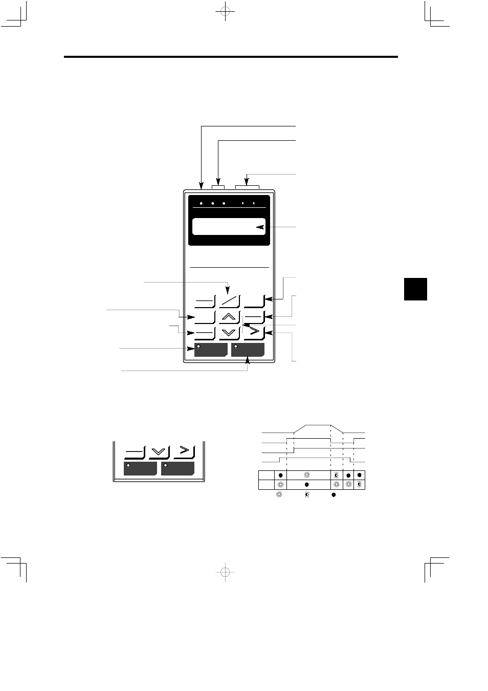
Fig. 5.1 shows the display section and operation keys of the Digital Operator, and Fig. 5.2 shows the LED dis-
play status of the RUN and STOP keys. Table 5.1 shows the displayed characters and the corresponding alpha-
bets and numbers, and Fig. 5.3 shows the display of bit selection signal.
LOCAL
REMOTE
Digital Operator
JVOP-132
DSPL
DATA
ENTER
JOG
FWD
REV
RESET
RUN
STOP
DRIVE FWD
REV
REMOTE
REF
SEQ
DRIVE
PRGM
Mode Display LED
Display
Display Selection Key
JOG
DRIVE FWD REV
REMOTE
REF
SEQ
Digital Operator Running Indication
Lights in the Digital Operator operation mode.
Rotation Direction Indication
FWD: Lights when forward run command is
input.
REV: Lights when reverse run command is
input.
Remote Mode Indication
SEQ: Lights when the motor rotates in the re-
verse direction.
Displays monitored values of speed reference
and function set values.
Depress this key to select display items.
Read/Write Key
Depress this key to display set values of
constants. Depress this key again to write
set values.
Numeral Change Key
Use these keys to change values such as set
values and constant Nos.
∧: Increment key
∨: Decrement key
Digit Selection Key
Use this key to select a position in a set val-
ue to be changed. The selected position
blinks. (Use this key to reset after and error
occurs.)
Run Command Key
These are run command keys when the drive is oper-
ated by the Digital Operator. These keys are effective
only in operation by Digital Operator.
STOP: Stop command
When STOP is depressed, the red LED on
the left part of the key lights.
RUN: Run command
When RUN is depressed, the red LED on
the left part of the key lights.
FWD/REV: Forward and reverse rotation switch
When this key is depressed, direction
of rotation is changed.
JOG: Jog run:
When this key is held down, jogging
is possible.
DRIVE/PRGM: Emergency stop
When this key is depressed, the op-
eration speed is reduced and stopped.
Then current is interrupted.
REF: — — —
Fig 5.1
Display Unit and Operation Keys of the Digital Operator
RUN and STOP LEDs light, blink, and go OFF depending on the status of operation.
JOG
FWD
REV
RESET
RUN
STOP
Motor Speed
ON
Blink
OFF
Speed Reference
LED
RUN
LED
STOP
[FWD]or [REV]
Main Circuit Power Supply
Fig 5.2
LED Display of RUN and STOP Keys
5