3 status display of sequence input signals, 4 details on sequence input signals, Rdy (operation ready signal) – Yaskawa Varispeed 626M5 User Manual
Page 78: Emg2 (emergency stop signal 2), Fwd/rev (forward signal and reverse signal)
4.1 Sequence Input Signals
4 -3
4.1.3 Status Display of Sequence Input Signals
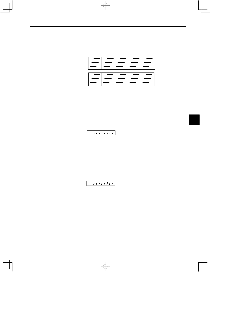
The ON/OFF status of input signals can be checked with the U10-09 and U1-19 operating status displays.
As explained below, the LED indicators of the Digital Operator show the status of each signal. Refer to
Chapter 5. Operating the Digital Operator for details.
U1-09
Input signal
status
U1-19
12-bit digital
reference
signal status
RDY
TLL
ORT
EMG
SSC
LGR
FWD
MGR
REV
CHW
THL
PPI
CHWA
DAS
RST
D1
D6
D11
D2
D7
D12
D3
D4
D9
D5
D10
D8
Notes: 1. The LED lights to indicate that the corresponding input signal is ON.
2. CHWA indicates the status of the auxiliary bits (2CN-12 and 2CN-13) of the electromag-
netic contractor for winding selection.
Fig 4.1
Display of Input Signal Status
4.1.4 Details on Sequence Input Signals
This section provides information on each signal of sequence input. The description is for a stand-alone
drive (M5A). Refer to the manual for the NC system (M5N) for sequence input signals and I/O addresses.
J
RDY (Operation Ready Signal)
RDY Function Selection: 6CN-6 will be the RDY signal if bit 2 of the C1-37 selection signals (SEL2)
is turned OFF.
Bit
2
C1−37
The RDY signal functions when 6CN-6 turns ON.
D
When the RDY signal us turned OFF during operation, the gate will be blocked instantly and the motor
current will be shut off.
D
While the RDY signal is OFF, the motor will not start unless the FWD and REV signals are turned OFF
together.
D
Always keep the RDY signal ON if the it is not being used. If a 0 V common or 24 V common input
is selected, connect pin 6 to pin 20. If the external common input is selected, turn the RDY signal ON
externally.
J
EMG2 (Emergency Stop Signal 2)
EMG2 Function Selection: 6CN-6 will be the EMG2 signal if bit 2 of the C1-37 selection signals (SEL2)
is turned ON.
Bit
2
C1−37
The EMG2 signal functions when 6CN-6 turns OFF.
D
The function of EMG2 is the same as the function of EMG (emergency stop signal). Refer to the de-
scription of EMG for details.
D
If EMG2 is used, there will be two emergency stop signals, EMG and EMG2.
D
The emergency stop operation will be performed if either EMG or EMG2 turns OFF.
D
To enable operation after clearing the emergency stop operation, turn ON both EMG and EMG2.
J
FWD/REV (Forward Signal and Reverse Signal)
The FWD signal will function when 6CN-8 turns ON.
The REV signal will function when 6CN-9 turns ON.
D
When the FWD signal is turned ON while the RDY and EMG signals are ON and the speed reference
is at a positive voltage, the motor will turn counterclockwise (motor viewed from the shaft end). When
the REV signal is turned ON, the motor will turn clockwise.
The rotation of the motor will be determined by the speed reference and operation signal in combina-
tion, as shown below.
4