Yaskawa Varispeed 626M5 User Manual
Page 276
Appendix
15.1.3 Squirrel Cage Induction Motor Characteristics
15 -4
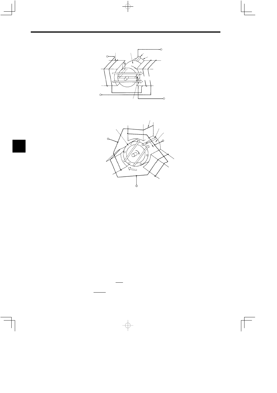
Magnetic field
winding
Stator
Flange
Commutator
Torque
Magnetic flux φ
m
Stator winding
+
+
−
−
Magnetic
field
(a) DC Motor
Stator winding
Rotator conductor
Rotator
Terminal V
Torque
Stator
Short-circuit ring
Terminal U
Terminal W
ω
r
ω
1
I
2
(b) Squirrel Cage Induction Motor
Magnetic
flux φ
m
Fig 15.5 Motor Model Diagrams
As shown in Fig. 15.5, the rotator is positioned inside the stator; i.e., within the rotation magnetic field.
When there is a difference between the angular velocity ω
r
of the rotator and the angular velocity ω
1
of
the rotation magnetic field, the rotator conductor cuts the alternating magnetic field of the differential an-
gular velocity. Consequently, secondary induction electromotive force E
2
is generated in the rotator con-
ductor due to the effect of magnetic field induction. Also, counterelectromotive force E
1
is generated in
the stator due to the effects of electromagnetic induction, and interlinkage between the magnetic flux of
the rotation magnetic field and the stator winding.
E
1
= kω
1
φ
m
= 2πkf
1
φ
m
Both tips of the rotator conductor are connected to the short-circuit ring, hence the name “squirrel cage.”
The secondary current I
2
thus flows due to the secondary induction electromotive force E
2
. This is equiva-
lent to the armature current of the DC motor.
Torque is generated using electromagnetic force proportional to the accumulation of secondary current I
2
and magnetic flux φ
m
in the same way as the DC motor, causing the rotator to rotate. The ratio of the rotator
to the speed differential of the rotator magnetic field is called the induction motor “slip.” If the rotator is
rotating at the same speed as the rotation magnetic field, the relative position of both will not change, so
the electromagnetic induction effect does not occur, and torque will not be generated. This is called syn-
chronous speed. Synchronous speed and slip are expressed using the following formulas.
Synchronous speed
N =
120f
P
(min
−1
)
Slip
S =
N − N
r
N
15