Yaskawa Varispeed 626M5 User Manual
Page 281
15.2 Basic Inverter Drive mechanics
15 -9
J
Inertial Moment Converted on a Motor Axis with a Gearbox
To obtain the required mechanical speed, a pulley and gears that can accelerate and decelerate are some-
times used. In Fig. 15.8, the load inertial moment converted to the motor axis as gear ratio a can be ex-
pressed using the following formula.
J
M
=
N
M
2
J
L
N
L
2
=
J
L
a
2
(kg
⋅
m
2
)
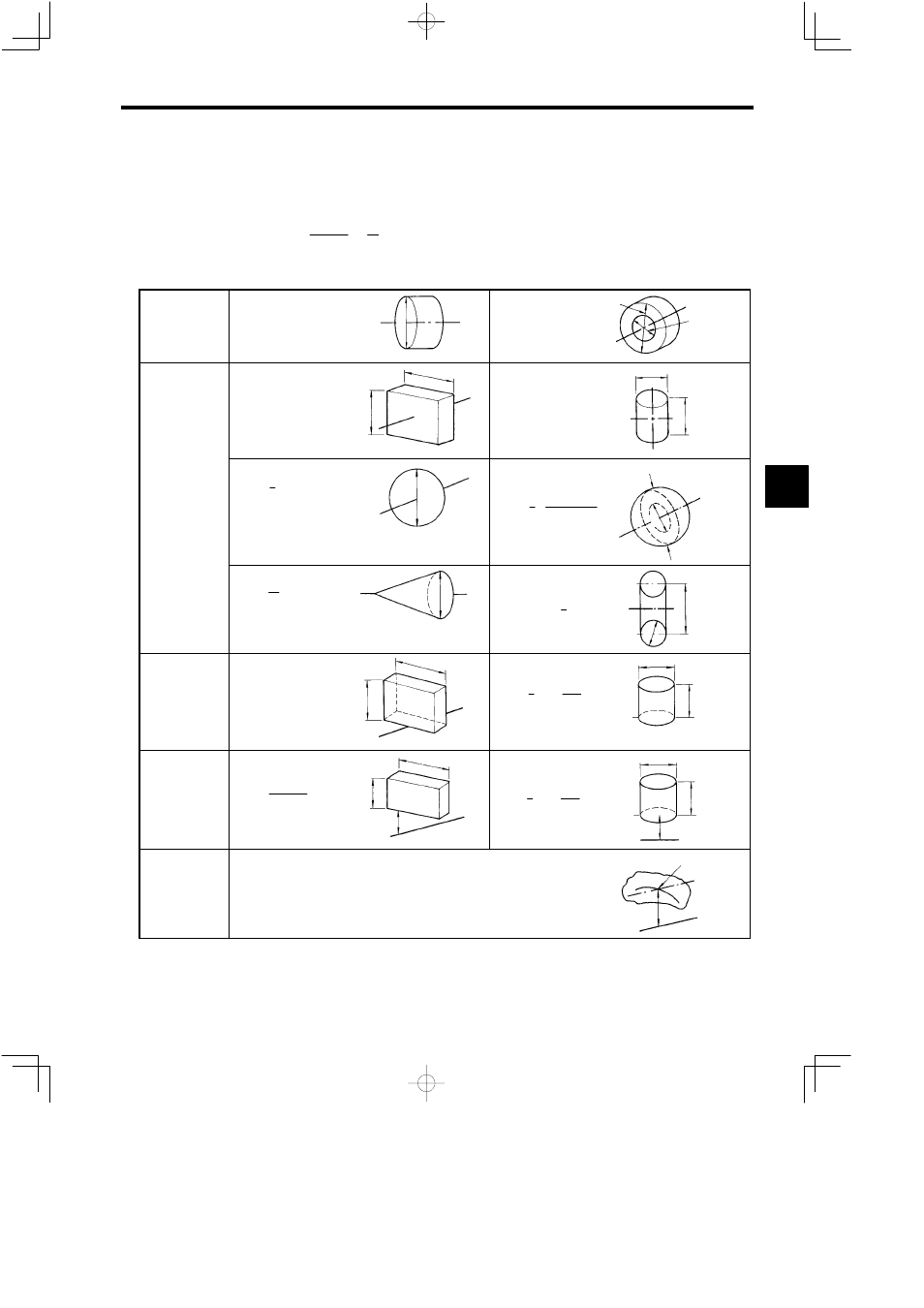
A simplified diagram of the rotation circumference is shown in Table 15.1.
Table 15.1 Simplified Diagram of the Rotation Circumference
Rotation axis is
the same as the
cylinder center-
line
Solid cylinder
(D
2
= D
0
2
∕2)
D
0
Hollow cylinder
D
2
= (D
0
2
+ D
1
2
)∕2
D
0
D
1
Rotation axis
passes through
the center of
gravity
Right-angle
box
D
2
= (b
2
+ c
2
)∕3
b
c
Cylinder
D
2
= L
2
∕3 + D
0
2
∕4
D
0
L
Sphere
D
2
= 25 D
0
2
D
0
Hollow sphere
D
2
= 25 ·
D
0
5
− D
1
5
D
0
3
− D
1
3
D
0
D
1
Cone
D
2
=
3
10 D
0
2
D
0
Circle
D
2
= D
0
2
+
3
4 D
1
2
D
0
D
1
Rotation axis is
at one tip
D
2
= (4b
2
+ c
2
)∕3
c
b
Right-angle
box
Cylinder
D
2
= 43 L
2
+
D
0
2
4
D
0
L
Rotation axis is
outside rotator
Right-angled
box
D
2
=
4b
2
+ c
2
3
+ 4 (bd + d
2
)
b
d
c
Cylinder
D
2
= 43 L
2
+
D
0
2
4
+ 4 (dL + d
2
)
D
0
L
d
General equation
when rotation
axis is outside ro-
tator
Center of
gravity
Rotation
axis
d
The general equation for the rotation circumference when the rotation axis
is outside the rotator is shown below.
D
2
2
= D
1
2
+ 4d
2
D
1
: Rotation circumference when the axis parallel to the rotation
axis and whose center of gravity passes through the rotation axis is
hypothetically the rotation axis.
15